Characteristic Specifications Supplemental Information
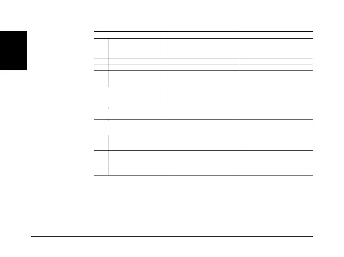
42 APx555 B Series Audio Analyzer: Analog I/O Specifications
555
Low Pass
10
ADC Bandpass (Maximum) No low pass filter is implemented,
bandwidth and response are limited
by the A/D and sample rate (SR)
–3 dB at 0.490 • SR, SR 216 kS/s
–3 dB at 260 kHz for 624 kS/s
–3 dB at 520 kHz for 1.248 MS/s
–3 dB at >1 MHz for 2.496 MS/s
20k (AES17), 40k (AES17) Special filters conforming with AES17
Butterworth F
LP
(–3 dB) = 20 Hz to 1 MHz, 8-pole ENBW 1.006 • F
LP
Elliptic F
LP
(–0.01 dB) = 20 Hz to 1 MHz,
8-pole; 0.01 dB pass band ripple;
–60 dB stop band
ENBW (1.012–1.062) • F
LP
(varies due to DSP warping)
Weighting A-wt, B-wt, C-wt, CCIR-1k, CCIR-2k,
CCITT, C-message, 50 s or 75 s
de-emph (with and without A-wt), or
None
Weighting filter is cascaded with both
high pass and low pass filters
Input Equalization
Arbitrary 30-pole input filter The EQ operates on any selected ana-
lyzer input channels.
IMD Measurement
Test Signal Compatibility
MOD & SMPTE Any combination of 40 Hz–1 kHz (LF)
and 1 kHz–60 kHz (HF) tones, mixed
in any ratio from 1:1 to 10:1 (LF:HF)
HF must be 6 • LF;
LF must be 500 Hz for SMPTE
DFD & CCIF
7
Any two-tone combination with mean
frequency of 250 Hz–60 kHz and a dif-
ference frequency of 80 Hz–2.0 kHz
F
diff
= |F2 - F1|
F
mean
= (F1 + F2) / 2.
(F
mean
/ F
diff
) must be 6
[see note 7}
DIM DIM-100, DIM-30, DIM-B, or DIM-B8