1
1
C
C
H
H
A
A
N
N
N
N
E
E
L
L
T
T
E
E
M
M
P
P
E
E
R
R
A
A
T
T
U
U
R
R
E
E
T
T
R
R
A
A
N
N
S
S
M
M
I
I
T
T
T
T
E
E
R
R
9
9
O
O
F
F
2
2
5
5
1
1
2
2
0
0
-
-
3
3
5
5
9
9
-
-
1
1
2
2
T
T
Y
Y
P
P
E
E
S
S
I
I
L
L
B
B
U
U
S
S
-
-
T
T
X
X
1
1
T
T
U
U
S
S
E
E
R
R
M
M
A
A
N
N
U
U
A
A
L
L
I
I
s
s
s
s
u
u
e
e
:
:
0
0
5
5
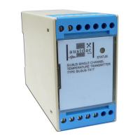
wire sensors for better accuracy. The figure below shows three and four wire PT100
sensors and typical lead identifications.
A
B
B
WHT
RED
RED
A
A
B
B
WHT
WHT
RED
RED
W4
W3
W2
W1
Figure 1 PT100 sensors and typical lead identifications
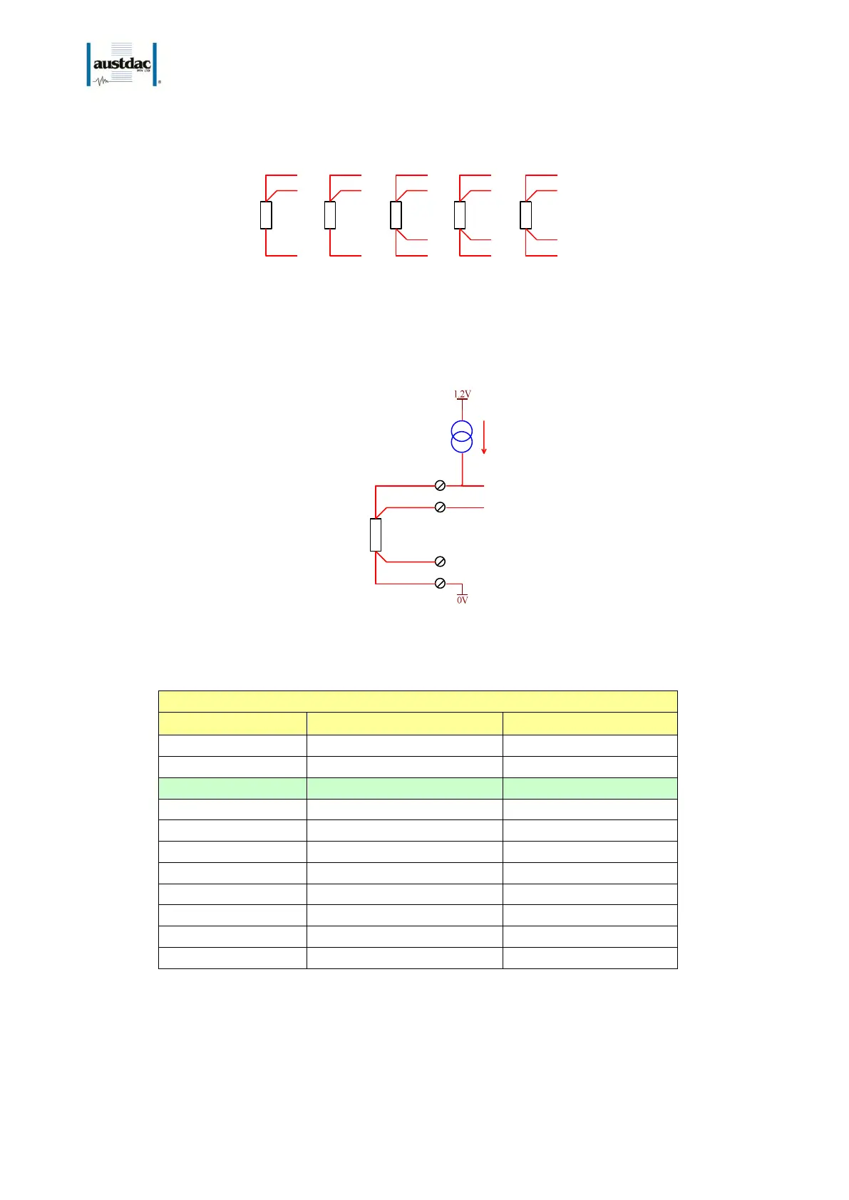
The SILBUS-TX1T temperature transmitter functions by driving a constant current of 200uA
out of terminal 8 through the PT100 sensor and back in through terminal 11. This current
will cause a voltage to appear across the sensor proportional to the sensor temperature.
8
9
10
DRIVE
20mV @ 0 degC
100R @ 0 degC
SENSE
EMC
200uA
TEMPERATURE
SENSOR
PT100
GND
11
Figure 2 Sensor input schematic
The sensor voltage and therefore temperature is measured at terminal 9 of the transmitter.
SILBUS-TX1T TEMPERATURE VS. INPUT VOLTAGE
Table 1 SILBUS-TX1T Temperature vs. Input voltage
The sensor voltage at terminal 9 does not include any error voltages introduced by the lead
from terminal 8 to the sensor. The sensor voltage at 0
o
C is 20mV.
The table above shows some typical temperatures, sensor resistances and SILBUS-TX1T
input voltages.