Illustrated fitting instructions
PLEASE TURN PAGE FOR INSTALLATION STEPS 8, 9 & 10
Note: If NOT using the ‘Caretaker’ feature - go to Step 6.
5.
6.
4.
2.
3.
1.
‘Caretaker’ feature‘Caretaker’ feature
‘Caretaker’ feature
Lockbody Installation
Cylinder installation
Preparation
ILLUSTRATED FITTING INSTRUCTIONS
ELEGANCE
for hinged security doors
E
T
H
L
C
I
S
Y
P
C
A
E
C
R
K
E
A
S
G
A
I
N
E
G
L
P
Select the exterior handle assembly which includes the
caretaker mechanism shown below.
When viewing the door from the outside of the house,
if the hinges are on the right hand side, rotate the ‘D’ pin towards the
right hand marks - RH. As shown below.
If the door hinges are on the left hand side, rotate the ‘D’ pin
towards the left hand marks - LH. As shown below.
‘D’ pin shown
rotated for
Right Hand
door
Caretaker
mechanism
‘D’ pin shown
rotated for
Left Hand
door
Slide the Caretaker spindle
vertically under the
caretaker cover
plate as shown
below.
Go to step 7
caretaker
spindle
caretaker
spindle fitted
cover plate
If not using the ‘caretaker’ feature, push the plastic plug which
has the Austral logo, into the square hole shown below.
Move the ‘D’ pin until the Austral logo on the plastic plug is vertical.
After adjusting, give the plug a final push to insure it is tight.
‘D’ pin
plastic plug with
Austral logo
square hole
(PK0234) ELEGANCE instructions (Trade A4) R5.cdr
7. Fit the correct Snib Lever
Select the interior handle assembly with snib lever hole.
Select the correct snib lever as shown in the box below.
Hold the snib lever horizontally and insert it into
the snib lever hole, turn it until vertical to secure it.
If the handle does not point towards the door
hinges, remove it from the handle plate and
exchange with the other handle.
While holding the snib lever vertical,
place the lever assembly against the door.
snib lever
towards door
hinges
interior handle
assembly
hollow snib, to u
with caretaker
se
snib with spindle, to use
without caretaker
or
Austral
Lock
is to assist in easy installation. - Do not
remove.
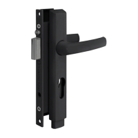
The sticker on the rear of the lockbody
ensure that the rear slide is pushed
completely down before assembling the
lockbody into the door cutout.
If the sticker has been broken or removed,
lockbody
sticker
rear slide
Depress the auxiliary bolt to ensure the
main bolt is fully extended.
Insert the key and turn to locked position.
Assemble the cylinder through the lock
so the cylinder protrudes equally from
both sides.
NOTE : the cylinder cam must rotate as
shown below. (cam turns towards front
of door)
Turn key to unlocked position and
remove key.
Insert #10 x 38mm cylinder screw & tighten.
NOTE : test, main bolt should not depress
main bolt
cylinder
screw
auxillary bolt
cam operation
cylinder
cylinder cam
accessory kit, be sure to follow the cylinder installation
procedure within the multipoint kit instructions.
IMPORTANT : If installing ELEGANCE with a multipoint
156mm
16mm
Door Cutout
Insert the lock body into the door cutout
Secure the lockbody with the two
#8x13mm lockbody screws.
lock body
lock body
screw
door cutout