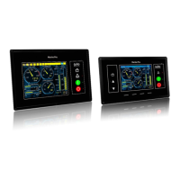
The device described in this manual is the Auto-Maskin Marine Pro 200 Series, an engine controller and remote panel system designed for marine applications. The series includes the DCU 210E Engine Controller, DCU 208E Engine Controller, RP 210E Remote Panel, RP 220E Remote Panel, and RP 206E Remote Panel.
Function Description
The Marine Pro 200 Series serves as a comprehensive engine management and monitoring system for marine engines. The DCU 210E Engine Controller is the primary building block, responsible for collecting and displaying engine sensor values, executing commands, and facilitating user interaction via a color touch screen. The DCU 208E Engine Controller offers similar functionality but without the integrated touch screen, making it suitable for smaller engine rooms where a remote panel is preferred.
The remote panels (RP 210E, RP 220E, RP 206E) extend the system's reach, allowing monitoring and control from various locations on a vessel, such as the bridge or other remote stations. These panels read their configuration from the connected DCU Engine Controller and automatically adapt to any changes. The RP 210E is designed to monitor and control a single DCU engine panel, while the RP 220E can monitor and control two. The RP 206E can monitor two DCU engine panels but does not offer start/stop control.
The system supports expansion through various RIO units (Remote I/O), enabling general I/O expansion, exhaust temperature monitoring, generator monitoring, and load sharing. An Ethernet switch is used to connect the DCU and RP units, simplifying configuration and allowing for IP-camera integration.
Usage Features
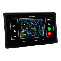
The DCU 210E and RP panels feature a touch screen interface for user interaction. Screen navigation is intuitive, with hot-spot areas predefined for specific functions. Pressing the left-hand side of the screen navigates to the previous page, while the right-hand side moves to the next. The center of the screen allows access to a miniature (thumbnail) view of all instrument pages for quick selection.
The DCU 210E also includes four physical buttons for quick access to main functions:
- Home Button: Always displays the first page of instruments.
- Alarm List Button: Shows the alarm list and allows users to exit it.
- Start Engine Button: Initiates the engine start sequence. This button can be configured as "latched" (completes the cycle with a single press after confirmation) or "hold-to" (requires continuous pressing until the engine starts). An "E-Start" (Emergency Start) option is available for rapid engine startup in critical situations, overriding prelube and activating shutdown override.
- Stop Engine Button: Initiates the engine stop sequence. Similar to the start button, it can be configured as "latched" (completes the cycle with a single press after confirmation) or "hold-to" (requires continuous pressing until the engine stops).
The system's operating mode can be selected from the settings menu:
- Automatic Mode: Accepts automatic start/stop commands. Local start/stop is possible if configured.
- Manual Mode: Does not accept external automatic start/stop commands. Local start/stop is possible if configured.
- Local Mode: Allows local operation only, blocking remote commands.
- Emergency Mode: Configured as a Combined Harbor/Emergency set, where shutdown channels only trigger alarms (except for overspeed).
- Harbor Mode: Available if configured as a Combined Harbor/Emergency set, with shutdown channels enabled and automatic start/stop disabled.
- Shutdown Override: All shutdown channels give an alarm only, except for overspeed.
The status bar at the top of the screen provides visual cues about the engine and panel status, using symbols to indicate modes like automatic, manual, local, emergency, harbor, and shutdown override. It also displays service interval warnings, overall system health (All OK), and gear positions (Neutral, Forward, Reverse, Engaged, Unknown).
The menu system offers various settings and controls:
- Settings: Allows adjustment of operating mode, enabling/disabling button beeps, selecting language, choosing metric or U.S. units, and setting wallpaper. It also provides options for connecting a PC and administration (deeper configuration).
- Screen Backlight: Adjusts screen intensity for different lighting conditions.
- Log & Counters: Provides access to engine operating hours (total, since start, since last reset), an event log (detailing when events appeared, were acknowledged, and disappeared), and engine service interval information.
- Controls: Accesses engine-related functions such as Engine Overspeed Test (temporarily lowers overspeed setpoint for testing), Gear Control (inspects transmission parameters and requests gear changes), and Prelube Override (skips prelube sequence for immediate engine start).
The remote panels also feature an "Active Station" function, allowing only one RP panel in the network to control the engine at any given time. Users can request or release active station status. Additionally, an "Operator Lock" feature prevents user input from the touch screen or buttons, indicated by a specific symbol. The RP panels can also display images from connected IP-cameras.
Maintenance Features
The system incorporates several features to aid in maintenance and troubleshooting:
- Alarm List: Displays all active and historical alarms. New events trigger a buzzer and cause the screen status bar to flash yellow (warning) or red (critical alarm/shutdown). The alarm list can be filtered to show "All Alarms" (alarms and diagnostics), "Panel Alarms" (alarms only), or "Diagnostics" (diagnostics only).
- Alarm Indication: Unacknowledged events are displayed in bold text, while acknowledged events are in normal text. Background colors provide quick visual identification of event types: white for diagnostic messages, yellow for warnings, red for alarms and engine shutdowns (with a STOP sign for shutdowns), and grey for unacknowledged events that have become inactive.
- Silence Buzzer: Entering the alarm list automatically silences the buzzer. If the buzzer sounds while in the alarm list, pressing the "Ack. Alarms" button silences it.
- Acknowledge Alarms: Individual alarms can be acknowledged by selecting them in the list and pressing "Ack. Alarms." All active alarms can be acknowledged by pressing and holding the "Ack. Alarms" button for one second.
- Troubleshooting Menu: Provides information for troubleshooting the panel itself and any connected RIO expansion units. It includes details on CPU-related information (temperature, frequency, load) and version information (panel hardware, software, kernel, and engine ECM software versions), including the panel's IP address for PC connection.
- Service Intervals: The "Log & Counters" menu displays how many hours remain until the next engine service, if service intervals are configured.