2
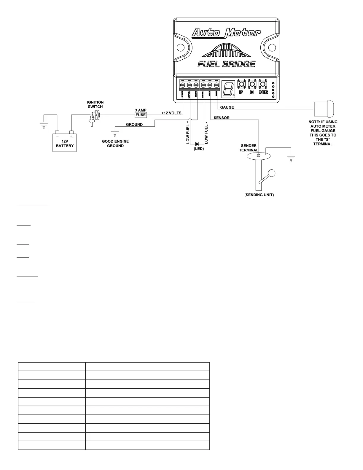
12v terminal: This gets wired to any 12v power source that turns on & off with the key. We recommend using the same power source as you
are using for your gauges. If wired to power separately, use an automotive 3a inline fuse.
Low+**: This is an optional terminal. If used, this will be the power wire (supplied from the module) to an LED indicator for low fuel level. (It
will not operate an incandescent bulb/indicator). See Step 5.
Gnd: Wire this to the same ground as you are using to ground your existing gauges. You may also ground this to engine ground.
Low-**: This is an optional terminal. If used, this will be the ground wire (supplied from the module) to an LED indicator for low fuel level. See
Step 5.
Sensor: This will be the wire coming from the fuel tank sender, also known as the signal wire. This wire will no longer be connected to your
gauge, or anything else. This will be wired only to the Sensor terminal of the Fuel Bridge. The other end of this wire remains on the fuel
sender.
Gauge: This wire will be the new sender output wire from the Fuel Bridge, to the “S” terminal on an Auto Meter gauge (or signal/sender
terminal on a non-Auto Meter gauge).
Step 4A, Programming:
Power must remain on during this process.
If you know your sender resistance range, proceed from here. If you do not know the range, or have a sender not listed in the list of sender
ranges, skip this step and proceed to step 4B.
Use the chart below to determine the option number for the various resistance ranges.
Option Number Sender type (resistance range)
1 240-33
2 0-90
3 0-30
4 16-158
5 73-10
6 73-10 non linear
7 10-180
8 40-250
A Learning (0-1k/1k-0)
 Loading...