7-14
CONNECTION OF SERVICES
3.2 Residual Current Device & Miniature Circuit Breakers
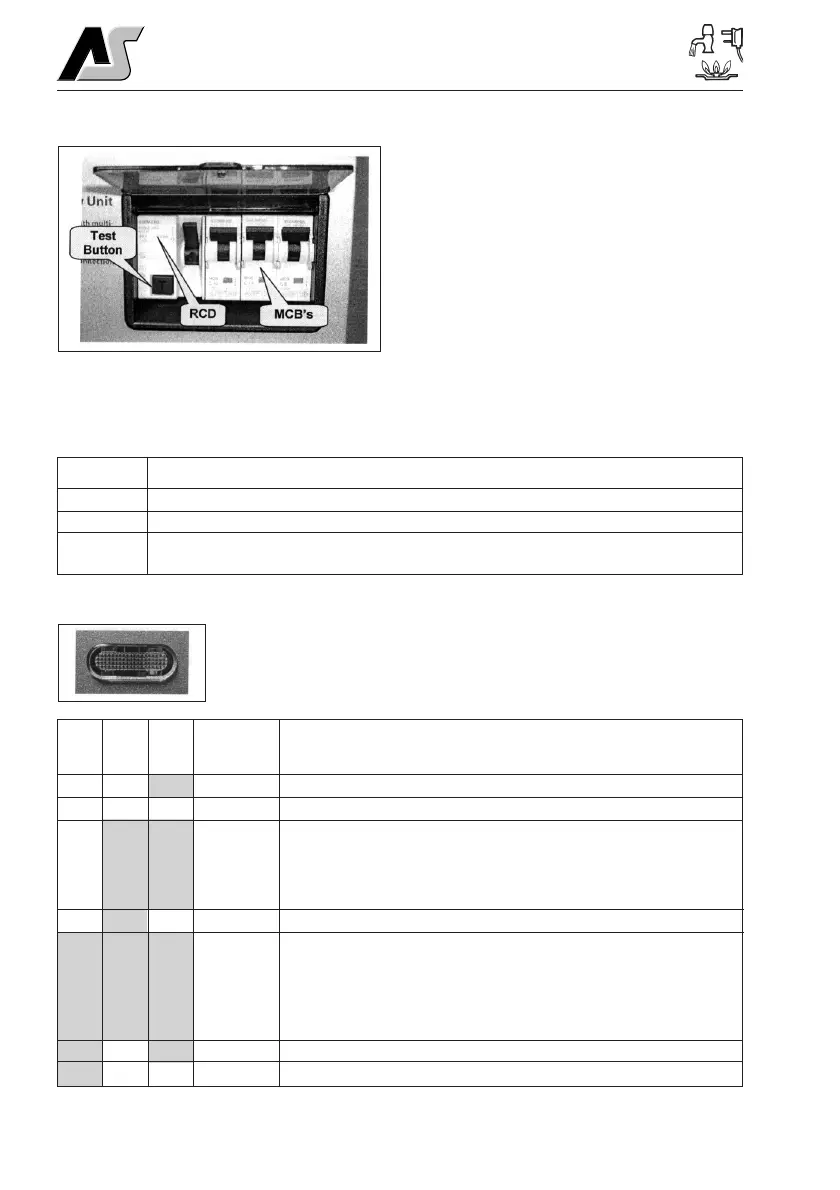
The Residual Current Device (RCD) is basically
provided to protect the user from lethal electric
shock. The RCD will turn off (trip) if the current
flowing in the live conductor does not fully return
down the neutral conductor, i.e. some current is
passing through a person down to earth or
through a faulty appliance.
To ensure the RCD is working correctly, the test
button should be operated each time the vehicle
is connected to the mains supply (see section 5.1)
The Miniature Circuit Breakers (MCB’s) operate in
a similar way to traditional fuses and are provided to protect the wiring installation from overload
or short circuit. If an overload occurs the MCB will switch off the supply. If this occurs you should
investigate the cause of the fault before switching the MCB back on.
The following table shows the rating and circuit allocation for the three MCB’s
3.3 System Monitor
The system monitor circuit checks the power supply key components to
ensure optimum operation. The current status is displayed on the front of
the PSU by the means of a dear indication that illuminates in different
colours depending on the PSU status.
MCB Rating Wire Colour Description
1 10 Amps White 230v Sockets
2 10 Amps White (Yellow for heater) Extra 230v Sockets / Heater
36 Amps Black (Blue for water heater) Fridge/Water Heater / 12v Charger
(internally connected)
Mains supply on, PSU status good.
Mains supply off, PSU status good.
Mains supply on, PSU in warning mode. In this mode the PSU will limit
the output current to protect the unit from damage. It is still safe to use
the unit but the fault should be investigated. Typical causes are battery
temperature sensor unplugged, cooling fan not working, internal
sensors disconnected or failed.
Mains supply off, PSU in warning mode.
Mains supply on, PSU in overheat failure mode. In this mode the PSU
will shutdown and all equipment will be switched off. The cooling fan
will continue to run until the unit cools down. Typical causes are short-
circuited DC output, battery connected in reverse, cooling fan failed,
cooling vents blocked / covered, problem caused by prolonged use in
warning mode.
Mains supply on, PSU in overheat failure mode.
Mains supply off, PSU in overheat failure mode.
Indication description
Right
Status
Left
Centre
Good
Good
Warning
Warning
Failure
Failure
Failure
––
––
–
G
G
G
G
R
R
R
O
O
O
O
–
––
–
–



 To Next Page