2
Device Operation
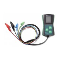
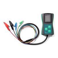
The device powers on automatically after connecting power to the B+ and B- leads. The test subject
selection menu will then appear. The desired parameter is selected by pressing the and buttons
and conrmed by a short press on the OK button to enter the testing mode.
After pressing OK, the display will present the following information:
1. voltage of the tested circuit (large digits)
2. required voltage (small digits on the top of the display)
3. alternator load DF/DFM (%)
The green RC and blue M cables should be connected to the correct pins in the voltage regulator’s
socket. Some of the regulators may require connecting other signals (usually B+) with a separate cable
to operate correctly.
The blue M cable can be left disconnected when testing in COM mode.
In the testing mode, buttons and will change the required voltage value. It should be monitored
whether changing the required voltage causes a corresponding change in the alternator/regulator output,
and whether the DFM reading matches the actual state.
Press and hold the OK button to leave the testing mode and return to the selection menu.