Do you have a question about the AUTODIAGGER AD100+ and is the answer not in the manual?
Lists supported testing protocols and compatible vehicle manufacturers for the AD100+ device.
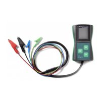
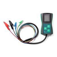
Explains the function of each colored test lead (RC, M, B+, B-) for connections.
Describes how the device powers on, navigates the selection menu, and enters testing mode.
Details the information shown on the display during testing: voltage, required voltage, and DFM.
Explains how to connect cables, including optional disconnection of the M cable, and how to exit testing mode.
Illustrates different connector configurations for COM, LIN, and BSS testing protocols.
Details the specific pin connections (COM, DFM, B+, B-) for alternators during COM, LIN, BSS testing.
Guides the user to select the COM function from the main menu and enter the testing mode.
Explains how to read and interpret the displayed voltage, DFM values, and manufacturer information during a COM test.
Shows the W LIN 15 S DFM connector for LIN 24V GRC testing.
Specifies the pin connections (W, LIN, 15, S, DFM, B+, B-) for LIN 24V GRC testing.
Instructs on selecting the LIN24 function from the main menu to begin testing.
Explains how to read and interpret the required voltage, actual voltage, and DFM values during LIN24 testing.
Displays the SIG connector and its pin layout (FR, S).
Details the pin connections (SIG, S, B+, B-) for Ford SIG testing.
Guides the user to select the SIG function from the main menu to perform the test.
Explains how to interpret the displayed voltage, DFM values, and alternator reaction during a SIG test.
Shows the D P connector used for Mazda P-D testing.
Details the pin connections (D, P, B+, B-) for Mazda P-D testing.
Instructs on selecting the P-D function from the main menu for testing.
Explains how to read and interpret the voltage and DFM values during a Mazda P-D test.
Shows the F(RVC) L(PCM) connector for General Motors L-RVC testing.
Details the pin connections (L(PCM), F(RVC), B+, B-) for GM L-RVC testing.
Guides the user to select the L-RVC function from the main menu for testing.
Explains how to interpret voltage and DFM values for the L-RVC test on GM alternators.
Displays the IG RLO L M connector used for Toyota RLO testing.
Details the pin connections (IG, RLO, L, M, B+, B-) for Toyota RLO testing.
Instructs on selecting the RLO function from the main menu to perform the test.
Explains how to interpret the voltage and DFM values during a Toyota RLO test.
Shows the B+ D D LIN GND plug and details i-STARS connections and power cables.
Guides the user to select the COM function for i-STAR testing.
Explains how to interpret voltage and DFM values during an i-STAR COM test.
Explains how to find and record the unique serial number of the AD100+ device.
Lists the necessary components and conditions for performing a software update on the AD100+.
Details steps 1-4 for powering up the device and accessing the update menu.
Outlines steps 5-7 for preparing the phone, enabling WiFi/NFC, and running the updater app.
Covers steps 8-10 for placing the phone on the device and transferring the software.
Details steps 11-16 for turning off/on the device, selecting "IMAGE UPDATE", and finishing the update.
Describes the EC5827 as a 20-piece alternator plug set suitable for test benches.
The Autodiagger AD100+ is a versatile handheld tester designed for diagnosing and testing alternator charging problems. It achieves this by simulating the digital signals typically sent from a vehicle's Engine Control Unit (ECU) to the alternator's voltage regulator. This capability allows the AD100+ to determine if the alternator's voltage regulator can communicate correctly with the vehicle's ECU and if the alternator responds appropriately to the simulated ECU input parameters.
One of the key features of the AD100+ is its flexibility in testing environments. It can be used to test an alternator while it is still installed on a vehicle, which is convenient for quick diagnostics, or on a test bench for more thorough evaluation. This dual-use capability makes it a valuable tool for both automotive technicians and workshops specializing in alternator repair.
The device supports a wide range of regulator testing protocols, making it compatible with numerous vehicle manufacturers. These protocols include COM, LIN, BSS(BSD) for Mercedes, Opel, Audi, BMW, Renault, VW, and Ford; 24V LIN GRC for Mercedes; SIG for Ford, Volvo, and Mazda; P-D for Mazda; L-RVC for GM, Vauxhall, and Opel; and RLO for Toyota. Additionally, with an optional software upgrade, it supports iSTARS Combined Alternator-Starters for PSA vehicles. This broad compatibility ensures that the AD100+ can be used across a diverse fleet of vehicles.
Operating the AD100+ is straightforward. The device powers on automatically once the B+ (positive) and B- (negative) leads are connected. Upon startup, the test subject selection menu appears, allowing the user to choose the desired testing parameter using the up and down arrow buttons, and confirming the selection with a short press of the OK button to enter the testing mode.
Once in testing mode, the display provides crucial information: the voltage of the tested circuit (shown in large digits), the required voltage (in smaller digits at the top of the display), and the alternator load, indicated as DF/DFM (%). The green RC cable and blue M cable are connected to the appropriate pins in the voltage regulator's socket. It's noted that some regulators might require additional signals, typically B+, connected via a separate cable for correct operation. When testing in COM mode, the blue M cable can be left disconnected.
During the testing process, the up and down buttons are used to change the required voltage value. Users are instructed to observe whether altering the required voltage results in a corresponding change in the alternator/regulator output and if the DFM reading accurately reflects the current state. To exit the testing mode and return to the main selection menu, the OK button must be pressed and held.
The AD100+ also boasts modern update capabilities. It can be updated wirelessly via NFC (Near Field Communication) using a compatible Android mobile phone. Alternatively, the device can be returned to Wood Auto for the update procedure. This ensures that the tester remains up-to-date with the latest protocols and features. The update process is designed to be safe, with the device retaining both the new and previous software versions for easy rollback if needed. To view the device's unique serial number and current software version, which are required for updates, the user powers on the device, presses the up arrow and OK buttons simultaneously while in the main menu, and holds them until the update menu appears.
Maintenance of the AD100+ is minimal. The device is designed to be resistant to common connection errors and typical voltage ranges, reducing the risk of damage from improper hook-up. It is also designed not to directly damage connected units, although testing an alternator without removing it from the vehicle, especially with voltages exceeding 15V, could potentially lead to electrical system errors. Selecting an incorrect testing function will generally only result in a lack of response from the alternator, rather than causing damage.
For storage, the AD100+ should be kept in a warm, dry environment. Cleaning the enclosure involves using a soft, moist cloth with a mild detergent, avoiding harsh chemicals like naphtha, paint thinners, or solvents, which could damage the display or coating. The device can be mounted on a test table, provided it's done without drilling holes or inserting screws into the enclosure.
The AD100+ is designed to work with connection wires up to 5 meters long and is compatible with 24V systems. If the display does not illuminate or show the main menu after connection, users are advised to check the connections, verify the system voltage, and ensure continuity of the wires. A common observation is that alternators with a COM interface may only start working after the required voltage is changed for the first time; this is normal behavior and indicates the alternator is functioning correctly. Similarly, if the device displays an error in COM mode when the alternator stops revolving, it's typically a "lack of revolutions" error, which is standard for digitally controlled voltage regulators and disappears once the rotor spins again, confirming proper operation. The device is not designed to test alternators with F1-F2 connectors, as these require an external voltage regulator and a different testing methodology.
| Model | AD100+ |
|---|---|
| Category | Test Equipment |
| Weight | 200g |
| Compatibility | OBD2 compliant vehicles |
| Functions | Read/Clear DTCs, Live Data, Freeze Frame, I/M Readiness, O2 Sensor Test, On-Board Monitor Test, Vehicle Info |
| Power Supply | Vehicle battery via OBD2 port |
| Operating Voltage | DC 8-18V |
| Operating Current | 100 mA |
| Operating Temperature | 0°C to 50°C |
| Supported Protocols | ISO15765-4 (CAN), ISO14230-4 (KWP2000), ISO9141-2, J1850 VPW, J1850 PWM |
| Storage Temperature | -20°C - 70°C |