©2009 The Hoffman Group L.L.C. All rights reserved. AUTMOTORCT - 2 of 2 Revised 2/17/09
The above instructions are for reference only. THG LLC is not responsible for any inaccuracies in the above instructions. THG LLC is also not responsible for any property damage or personal injuries resulting from the above
instructions. Installation by qualified automotive professionals is highly recommended.
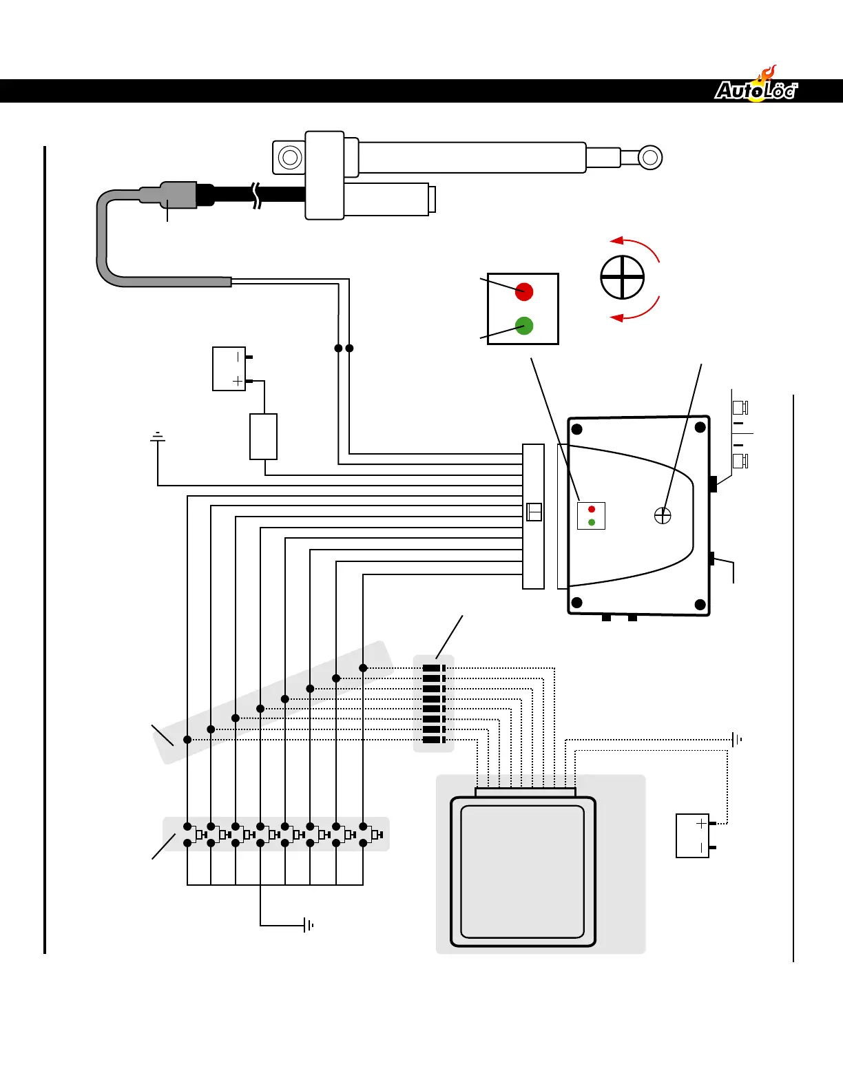
RESET
6A 10A
SENSITIVITY ADJUSTMENT
(remove cover to access)
PROGRAM UP
PROGRAM DOWN
BLUE/WHITE
GREEN/WHITE
Black
Red
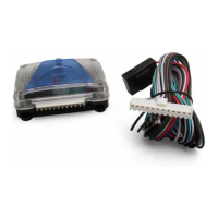
part#
LAPLUG
WHITE
DIODE
*
(1 or 2 amp.)
WHITE/BROWN
WHITE/BLUE
WHITE/BLACK
BROWN/WHITE
BROWN/GREEN
BROWN/BLUE
BROWN
15 Amp
Fuse
Battery
12V
Battery
12V
Ground
Ground
1
2
3
4
5
6
7
8
GROUND
INCREASEDECREASE
UP LED
(RED)
DOWN LED
(GREEN)
OPTIONAL REMOTE
CONTROL RECEIVER
WIRING DIAGRAM
NEGATIVE OUTPUTS CONECTIONS
(from optional remote control)
OPTIONAL MOMENTARY
TRIGGER BUTTONS
(part # s15)
*NOTE: If you are using a remote control system and the momentary trigger buttons on the same MotorCT trigger inputs (1-8), you
must diode isolate the negative outputs from the remote control system.
AUTKL 550 - 5 channel
AUTKL600 - 6 channel
AUTKL700 - 7 channel
AUTKL1000 - 10 channel
AUTKL1600 - 16 channel
AUTKL1800 - 18 channel
USER GUIDE AND INSTALLATION MANUAL
WWW.AUTOLOC.COMTECH SUPPORT: 503.693.1918
 Loading...