Do you have a question about the Automated Logic RS Standard and is the answer not in the manual?
Explains Celsius and Fahrenheit display accuracy for digital readouts.
Details how to adjust occupied time, including cancellation.
Describes using Warmer/Cooler buttons to adjust zone setpoints.
Use specified sensor cable for signal integrity; avoid contact with foil shield.
Procedure for connecting the Rnet Access Cable to the sensor port.
Diagnosing issues when the sensor shows no power.
Troubleshooting sensor communication problems.
Checking wiring for correct communication and status display.
The RS Standard and RS Pro are thermistor-based temperature sensors designed for use with ZN-Line, SE-Line, and ME-Line controllers. These devices are integral components of an Rnet sensor network, which can support up to four RS Standard sensors and one RS Pro sensor.
The RS Standard sensor is a basic temperature sensing unit. Its primary function is to provide temperature data to the connected controller. By default, an RS Standard sensor is assigned address 1. To change this address, the user must unscrew two circuit board screws located behind the cover plate and remove the cover. Inside, a jumper can be set to address 2, 3, or 4. After setting the desired address, the circuit board and cover plate are reattached. This addressing mechanism allows multiple RS Standard sensors to operate within the same Rnet network without conflict. The RS Standard does not feature a digital display or user-interactive controls, making it a straightforward, data-gathering device.
The RS Pro sensor offers enhanced functionality, providing occupants with setpoint and override control within limits established by the building management system or operator. Unlike the RS Standard, the RS Pro does not require addressing, as only one RS Pro sensor is permitted per Rnet network.
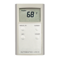
The RS Pro features a digital display that shows temperature values. For Celsius, values are displayed to the nearest 0.5 degree, while for Fahrenheit, values are shown to the nearest full degree. The display also indicates occupancy status, which can be triggered by a regular schedule or a manual override. An alarm bell icon may also appear on the display, signaling an alert condition.
User interaction with the RS Pro is facilitated by several buttons. The "Manual On" button allows occupants to manually override the scheduled occupancy. Pressing this button displays the override time. Subsequent presses increase the occupied time. To cancel the override, the button is pressed until "0" is displayed. After pressing "Manual On," the display reverts to showing the current zone temperature after a five-second delay.
Setpoint adjustment is managed through "Warmer" and "Cooler" buttons. When either button is pressed, the display shows the average of the current heating and cooling setpoints. Pressing the button again adjusts both setpoints simultaneously, raising or lowering them by an amount configured on the RS microblock's Properties page. This action updates the displayed average setpoint. For example, if the cooling setpoint is 76 and the heating setpoint is 70, the average is 73. If the setpoint adjustment is 2, pressing "Warmer" twice would raise the cooling setpoint to 78, the heating setpoint to 72, and the average setpoint to 75. This provides occupants with a degree of personalized control over their environment while maintaining system-defined boundaries.
The "Info" button on the RS Pro cycles through various displays, providing occupants with additional information. These displays include the current zone temperature, the outside air temperature (if enabled), the remaining override time in minutes, the current heating setpoint, and the current cooling setpoint. This allows occupants to quickly access relevant environmental data and system statuses.
Maintenance and troubleshooting for both RS Standard and RS Pro sensors involve wiring and communication checks. The Rnet network communicates at 115 kbps and supports daisy-chain, star, or hybrid configurations. The wiring specifications require 18 AWG stranded copper wire with specific insulation and jacket properties to ensure signal integrity. Proper wiring involves stripping the outer jacket and inner insulation carefully to avoid nicking the wires. For the terminal block connection, it's crucial to ensure that no more than 1/8 inch (3 mm) of bare communication wire protrudes, and that drain or shield wires are twisted together and inserted with the black ground wire. Incorrect wiring can lead to communication issues.
Mounting the sensor involves connecting the terminal block, with wires facing up, to the back of the sensor's circuit board. The sensor's cover is then replaced, and a setscrew is turned one full turn counterclockwise to secure the cover.
Both RS Standard and RS Pro sensors include an Rnet port, which allows a laptop computer to connect to the system for test and balance procedures. This port facilitates access to a WebCTRL system, enabling technicians to conduct diagnostics and configuration. Connecting an Rnet Access Cable involves holding the cable end horizontally, prongs upwards, under the Rnet port, hinging the prongs into the front of the port, and then pushing the back of the cable end up until it clicks into a vertical position. This connection requires an APT (Automated Logic Programmer Tool) and its cables to link to the laptop.
Troubleshooting common issues includes diagnosing power and communication problems. If an RS Standard has no power, its circuit board LED will not light. If it has power but is not communicating, the LED will blink once per second. When correctly wired and communicating, the LED blinks 2.5 times per second. For an RS Pro, no power results in a blank LCD display. Power with no communication causes the LCD to display all display elements. When correctly wired and communicating, the LCD displays only the temperature and current status, indicating proper operation. These visual cues assist in quickly identifying and resolving sensor issues.
| Category | Temperature Controller |
|---|---|
| Manufacturer | Automated Logic |
| Power Supply | 24 VAC/VDC |
| Input Type | Thermistor |
| Display | LCD |
| Operating Temperature | 0° to 50°C (32° to 122°F) |