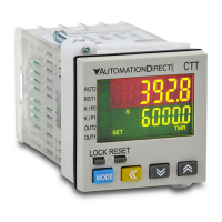
P.2
Counter Example:
1-Stage Counting (
Sta6e1
)
Counting Up (
UP
)
Using the counter feature of the CTT to count the total number of pieces in a box to signal a conveyor to advance to the
next station.
Counting Input
Output 1
Reset
Count
Input Mode
Counting Up (
UP
)
With the input signal OFF at input CP2, each leading edge of the input signal at CP1 will increment the count present
value PV by 1.
Output Mode
Mode F (
F
)
When the count present value PV counts up to the count setting value SV both outputs 1 and 2 will turn ON.
The count PV will continue to increment with each input signal. The leading edge of “a reset” input signal at RST1 will
turn OFF both outputs, reset the count PV to 0, and prohibit an input signal from incrementing the count PV. The trailing
edge of the “reset” signal at RST1 enables counting to begin.
Keypad set up of the parameters in the Counter for 1-Stage Counting:
Select functions: There are 4 modes in CTA, (left to right) timer, counter, tachometer and timer + counter.
–FunC Cont taCh –mixtime
Select counter functions: 1-stage counting, 2-stage counting, batch counting, total counting, dual counting.
Ä
CntFun sta6e1 sta6e2 batCh total dual
C–inPt
––UP down ud–a ud–b ud–C
Select input modes: counting up, counting down, command counting up/down, individual counting up/down,
quadrature input.
C–otmd
F nC rkp
q
a
s
t
d
Select output modes: CTA offer 11 output modes, among which mode S, T and D are only valid with input modes
Ud_A, Ud_b and Ud_C.
Select counting speed: Maximum 10Kcps; others 5K, 1K, 200, 30 and 1cps.
C–Sped –10k ––5k ––1k –200 ––30
t–out1
Pulse width of output 1: The default output time is 0.02 second. When the parameter is set to 0.00 second, the
output status will continue.
–––1
–002 –000
t–out2
Pulse width of output 2: This paramter is adjustable according to different output modes selected. If the output mode is C,
the default output time will be 0.02 second, When the parameter is set to 0.00 second, the output status will continue.
–002 –000
–point
Set up the position of decimal point: 0 (no decimal point), 1 (one digit after decimal point), 2 (two digits after decimal
point), 3 (three digits after decimal point).
0 12 3
psCale 1000
Set up pre-scale value: 1.000 (default 1:1) Range: 0.001 to 99.999
–pwers
Save the data while switching off the power: When SAVE is selected, the PV will be saved; when CLEAR is selected,
the PV will not be saved.
Clear save
–rtsr
Set up minimum width of reset signal: Default = 20ms; 1ms is also selectable
––20 –––1
inptlC
Select input signal types: NPN and PNP
–npn –pnp
Ä
Ä
Ä
Ä
Ä
Ä
Ä
Ä
Ä
Ä
Ä
or or or or
or or
or
or
or
or
or
or or
or
or
or
or
or
or or or
or
or
or
or or
or
or
or
or
or or
or
or
or
or oror or
or
or or
oror
or or
To enter the page for parameter setting of the counter, press
Ä
for the main menu for more than 3 seconds. After the setup
is completed, press
Ä
for more than 3 seconds under any of the parameter page you are in and return to the main menu.
Timer Example:
A basic Timer used to control a clamp time of a compression model press.When the operator signals the
mold is loaded with material by pressing the start button the hydraulic cylinder closes the press to make a
limit switch which starts the CTT timing. Upon completion of the timer cycle Output 1 is turned on and the
press is opened by the hydraulic cylinder.
Signal On Delay 1 (
Sond1
)
With power applied to the CTT, the leading edge of an input signal at START will begin the
timing period setting value SV (timing up or down based on parameter (
t modE
). At
the end of the timing period both outputs will turn ON momentarily for the time set in the output pulse
width parameter (
tout1
) or will be maintained ON if the output pulse width parameter (
tout1
) is set
to 0.00. The trailing edge of the “start” signal has no effect on the outputs or timing period. The leading
edge of an “reset” input signal at RST1 will turn OFF the outputs and reset the timing period.
The “reset” signal minimum pulse width is set by reset pulse width parameter
(
rtSr
) or DIP Switch 8. The leading edge of an “pause” signal at GATE will pause the
timing period after it has been started. The timing period will continue after the trailing edge of the
external switch “pause” (Gate) signal. When power is removed, both outputs will turn OFF and the
timing period will be reset.
Output 1
Reset
ut
ut 1
ese
Limit
Switch
Starts
Timer
To enter the page for parameter setting of the timer, press
Ä
in the main menu for more than 3 seconds. After the
setup is complete, press
Ä
for more than 3 seconds under any of the parameter page you are in and return to the
main menu.
time Cont taCH –mix
t–mode
–up down
t–otmd
sond1 sond2 soffd –son
pond
t–out1
–002 –000
Ä
pond
–rCy rCyh rCy2 sConsto
Select funtions: There are 4 modes in CTT, (left to right) timer, counter, tachometer and timer + counter.
Select timer mode: timing up and timing down
t–unit
s–001 s–01 –s–1 ms–001
ms–01m–01
–m–1 hms–1 hm–1–h–1
Select output modes: There are 12 output modes in the timer. The user can choose the mode that best
meets the demand.
Select display unit: the min. unit 10ms to the max. unit hour are selectable. Refer to table below.
Select pulse width of output 1: The default output time is 0.02 second. When the parameter is set to 0.00
second, the output status will continue.
–rtsr
––20 –––1
Ä
Select min. width of reset signal: The defaul value is 20ms; can be set to 1ms.
inptlC
–npn –pnp
Ä
Select input signal types: NPN and PNP.
Back to Top
or
or or
or
or or
or
or or or
or
or
or
or
or
or
or or or or
or or
or
or
oror
or
ororor
or or or or
Keypad set up of the parameters in the Timer:
Tachometer Example:
Using PSCALE to convert pulses into engineering units
The PSCALE feature of the CTT is very useful in converting the pulsed signal from an encoder or sensor into some
usable unit of measurement.
For example if one was to connect a proximity switch to the CTT to monitor the speed of a motor using a sensing gear
there is a simple calculation to convert the pulses from the sensor to Motor RPMs.
Using this formula you can calculate a PSCALE value to change a pulse signal into RPMs. First obtain the pulses per
revolution (ppr) or number of teeth on the sensing gear for example in the illustration below there are 38 teeth on the
gear or 38 ppr. If the gear is coupled directly to the motor this is all that is required to perform the calculation.
PSCALE = 60/ppr or 60/38
PSCALE = 1.579
With the PSCALE set to 1.579 for every 38 input cycles the CTT will display a value of 1.
Select functions: There are 4 modes in CTT, (left to right) timer, counter, tachometer and timer + counter.
–FunC
Cont taCh –mixtime
Select rotation speed: Maximum 10Kcps; others 5K, 1K, 200, 30 and 1cps.
C–Sped
–10k ––5k ––1k –200 ––30
–point
Set up the position of decimal point: 0 (no decimal point), 1 (one digit after decimal point), 2 (two digits after decimal
point), 3 (three digits after decimal point).
0 12 3
psCale
Set up pre-scale value: 1.000 (default 1:1) Range: 0.001 to 99.999
St–taC
Set up the delay time after switching on the power: 0.0 (default). The tachometer will start to run when the set delay
time is due after the power is switched on. Setup range: 0.1 to 99.9 seconds
––00
St–Av6
Set up average value of the input filter: The average value is for making the present value detected by the tachometer
more stable.
The setup range is 0 to 3 (1 = 2 data, 2 = 4 data, 3 = 8 data). For example, if you select “3”, the system will
average the 8 present values from the tachometer to make the present value displayed on the screen more stable.
–rtsr
Set up minimum width of reset signal: Default = 20ms; 1ms is also selectable.
––20 –––1
Select output modes: There are 4 output modes, 2Lo1Lo, 2Lo1Hi, 2Hi1Lo, and 2Hi1Hi, For example, when you select
2Hi1Lo, and assume the first set value is 100 (2Hi) and the second 50 (1Lo), the output value of the tachometer will be
below 100 (2Hi) and above 50 (1Lo) and CTT will not perform an output. If the set value exceeds the range, CTT will
perform an output.
taotmd
2Lo1Lo 2Lo1Hi 2Hi1Lo 2Hi1Hi
–––1
1000
0 12 3
InptlC
–npn –pnp
Select input signal types: NPN and PNP.
or
or
or
or
or
or
or
or
or or
or or
or
or
or or or or or
or or
ororor
or
or
or or
Data Sheet: CTT-CTT
Copyright 2017, Automationdirect.com Incorporated/All Rights Reserved Worldwide
Additional Help and Support
• For additional technical support and questions, call our Technical Support team @ 1-800-633-
0405 or 770-844-4200
• For additional product information, please download the complete product manual which can be
found at: www.AutomationDirect.com
Keypad set up of the parameters in the Tachometer:
For a full set of Demo and Set Up videos for the CTT units please
scan the QR code or follow the link below.
https://www.automationdirect.com/videos/
home?t=link&cat1=60
 Loading...