EasyManua.ls Logo

AutomationDirect CTT Series - User Manual

AutomationDirect CTT Series
2 pages
Print Icon
To Next Page IconTo Next Page
Loading...
3505 HUTCHINSON ROAD
CUMMING, GA 30040-5860
Digital Counter/Timer/Tachometer
CTT Series
The CTT series is an extremely versatile multi-function device that is easily configured for operation as a digital counter, timer,
combination timer + counter, or tachometer. Both voltage and non-voltage inputs are accepted from a wide variety of sensor types
with NPN, PNP, or dry contact outputs. The first output on the CTT is a single-pole, single-throw relay and NPN transistor
that operate concurrently. The second CTT output can be ordered as either a single-pole, double throw relay or NPN transistor.
Parameters are easily set using the externally accessible DIP switches or the lockable keypad. The double-line, 6-digit, two-color
LCD display shows the counter, timer, or tachometer present values, setting values and menu parameters during set-up. Additional
individual indicators are provided for inputs, outputs and functions. The standard 1/16 DIN size, included panel mounting clip
and gasket make panel mounting a snap. The CTT is available in 120-240VAC and 24VDC powered models.
For additional product information, please download the complete product manual which can be found at:
www.AutomationDirect.com
Description:
MODE
CTT
AUTOMATIONDIRECT
.com
RST2
RST1
K/P2
K/P1
OUT2
OUT1
LOCK RESET
Quick Start Guide
Box Contents and Unpacking Instructions
After receiving the CTT Counter/Timer/Tach, please check for the following:
Make sure that the package includes the CTT Counter/Timer/Tachometer, the
mounting bracket and hardware, and the Quick Start Guide.
Inspect the unit to insure it was not damaged during shipment.
Make sure that the part number indicated on the label corresponds with the
part number of your order.
If anything is missing or damaged, immediately call the AutomationDirect returns
department @ 1-800-633-0405.
For additional product information, please download the complete product manual
which can be found at: www.AutomationDirect.com
~ WARNING ~
Thank you for purchasing automation equipment from Automationdirect.com™, doing business as AutomationDirect. We want your new automation
equipment to operate safely. Anyone who installs or uses this equipment should read this publication (and any other relevant publications) before installing
or operating the equipment.
To minimize the risk of potential safety problems, you should follow all applicable local and national codes that regulate the installation and operation of
your equipment. These codes vary from area to area and usually change with time. It is your responsibility to determine which codes should be followed,
and to verify that the equipment, installation, and operation is in compliance with the latest revision of these codes.
At a minimum, you should follow all applicable sections of the National Fire Code, National Electrical Code, and the codes of the National Electrical
Manufacturer’s Association (NEMA). There may be local regulatory or government offices that can also help determine which codes and standards are
necessary for safe installation and operation.
Equipment damage or serious injury to personnel can result from the failure to follow all applicable codes and standards. We do not guarantee the prod-
ucts described in this publication are suitable for your particular application, nor do we assume any responsibility for your product design, installation, or
operation.
Our products are not fault-tolerant and are not designed, manufactured or intended for use or resale as on-line control equipment in hazardous environ-
ments requiring fail-safe performance, such as in the operation of nuclear facilities, aircraft navigation or communication systems, air traffic control, direct
life support machines, or weapons systems, in which the failure of the product could lead directly to death, personal injury, or severe physical or environ-
mental damage (“High Risk Activities”). AutomationDirect specifically disclaims any expressed or implied warranty of fitness for High Risk Activities.
For additional warranty and safety information, see the Terms and Conditions section of our catalog. If you have any questions concerning the installation
or operation of this equipment, or if you need additional information, please call us at 770-844-4200.
This publication is based on information that was available at the time it was printed. At AutomationDirect we constantly strive to improve our products
and services, so we reserve the right to make changes to the products and/or publications at any time without notice and without any obligation. This
publication may also discuss features that may not be available in certain revisions of the product.
Trademarks
This publication may contain references to products produced and/or offered by other companies. The product and company names may be trademarked
and are the sole property of their respective owners. AutomationDirect disclaims any proprietary interest in the marks and names of others.
Copyright 2011-2012, Automationdirect.com™ Incorporated
All Rights Reserved
No part of this manual shall be copied, reproduced, or transmitted in any way without the prior, written consent of Automationdirect.com™ Incorporated.
AutomationDirect retains the exclusive rights to all information included in this document.
CTT- AN- D24
D24: 24VDC powered
A120: 100-240VAC powere
d
AN: NPN output 2
1C: SPDT relay output 2
Counter/Timer/Tachometer
Model Number Explanation
Input Specification
Agency Approvals
Country of Origin
Label Information
General Specifications
MODE
45.00
[1.77]
45.00
[1.77]
65.00
[2.56]
60.00
[2.36]
1
6
11
2
7
12
3
8
13
4
9
14
5
10
15
44.80
[1.76]
44.80
[1.76]
6.35
[0.25]
44.80
[1.76]
CTT
AUTOMATIONDIRECT
.com
RST2
RST1
K/P2
K/P1
OUT2
OUT1
LOCK RESET
44.80
[1.76]
79.35
[3.12]
6.35
[0.25]
47.85
[1.88]
47.85
[1.88]
79.35
[3.12]
Dimensions [mm] inch
0V CP1
CP2/
GATE
+12V RST1
RST2/
START
0V CP1
CP2/
GATE
+12V RST1
RST2/
START
N.O.
COM
LOAD +V0V
N.C.
N.O.
COM
CTT-1C-D24
OUT
2
21.6 to
26.4 VDC
Load
21.6 to
26.4 VDC
OUT
1
OUT
2
CTT-AN-D24
N.O.
COM
0V
LOAD
OUT
1
0V
LOAD
0V CP1
CP2/
GATE
+12V RST1
RST2/
START
0V CP1
CP2/
GATE
+12V RST1
RST2/
START
N.O.
COM
LOAD +V0V
CTT-1C-A120
OUT
2
AC100 to 240V
50/60Hz
Load
AC100 to 240V
50/60Hz
OUT
1
OUT
2
CTT-AN-A120
N.O.
COM
0V
LOAD
OUT
1
0V
LOAD
N.O.
COM
POWER SOURCE
12VDC @ 100mA
POWER SOURCE
12VDC @ 100mA
POWER SOURCE
12VDC @ 100mA
POWER SOURCE
12VDC @ 100mA
N.C.
109
321
1514
876
131211
54
10
9
321
15
14
876
13
1211
54
10
9
1514
876
131211
54
10
9
321
15
14
876
131211
54
321
+
-
+
-
S
S
Terminal Layout
Reset 2 indicator
Reset 1 indicator
Key protect 2 indicator
Output 2 indicator
Key protect 1 indicator
Output 1 indicator
Special function indicator
Lock key
Reset key
Mode and number shift key
PV(Present Value) display
SV(Set Value) display
Timer function indicator
Counter function indicator
Tachometer function indicator
Up/Down key
CTT
A
UTOMATION
D
IRECT
.com
LCD Display and Indicators
RST 1/2
Light on when reset signal is detected
BATCH
“Batch Counting Mode” in Counter
K/P 1/2
Light on when key-protected mode is enabled
SET 1 2
SV1, SV2 display
OUT 1/2
Light on when output is executing
TAC
Light on in Tachometer function
H M S
Hour, minute, second, unit of timer, displayed in Timer function
CNT
Light on in Counter function
TOTAL
“Total Counting Mode” in Counter function
TMR
Light on in Timer function
Key Operation
, .
Increase and decrease SV or change paramter settings
´
Left move 1 digit of the selected digit. The indicator of the selected digit will flash.
Ä
Save the set parameters or switch among functions.
LOCK
Prevent settings from being changed. Key-protected mode still works after power cycle. Press LOCK to enter key-protected mode. In non-key-protected status, press
LOCK to enter Lock 1, press LOCK again to enter Lock 2. Press Ä and ´ at the same time to disable key-protected mode. LoC1 (Lock 1) disables the functions
of all keys. LoC2 (Lock 2) allows users to change SV and functions of RESET remain. LOCK only functions in non-key-protected status.
RESET Clear and reset PV.
Modes: Operation Mode and Configuration Mode
Operation
When the power is on, the timer/counter/tachometer is in the operation mode. Press ,. to change SV, or ´ to select to change digit. The indicator of the se-
lected digit will flash. After the change is made, press Ä to save the setting. If SV or paramters are not changed, press Ä once to switch between SET1 and SET2.
Configuration
Press Ä in operation mode for more than 3 seconds to enter configuration mode. Press Ä once to switch among parameters. To return to operation mode, press
Ä for more than 3 seconds.
Display, Indicators and Keys
Counter Functions Counter Input Modes Counter Output Modes
1-Stage Up
Select from eleven (11) different
output modes (F, N, C, R, K, P,
Q, A, S, T, D)
2-Stage Down
Batch Up / Command Down
Total Up/ Down
Dual Quadrature
Addition
Subtraction
Timer Functions (Up or Down)
Signal On Delay 1 Repeat Cycle
Signal On Delay 2 Repeat Cycle Hold
Signal Off Delay Repeat Cycle 2
Signal On Signal Cumulate
Power On Delay Signal Twin On-Start
Power On Delay Hold Signal Twin Off-Start
Timer + Counter
Timer Functions
(Up or Down)
Counter Input Modes Counter Output Modes
Signal On Delay 1 Up
Select from eight (8) different out-
put modes (F, N, C, R, K, P, Q, A)
Signal On Delay 2 Down
Signal Off Delay
Signal On
Power On Delay
Power On Delay Hold
Repeat Cycle
Repeat Cycle Hold
Tachometer Output Modes
Select from four (4) different output modes
2Lo/1Lo
2Lo/1Hi
2Hi/1Lo
2Hi/1Hi
Digital Counter / Timer / Tachometer General Specifications
Input Power Requirements
100 to 240 VAC 50/60 Hz 24 VDC
Operation Voltage Range
85 to 264 VAC 21.6 to 26.4 VDC
Power Consumption
Less than 10VA
Power Source
12VDC w10%, 100mA
Display
Double-line, 6-digit LCD display (SV = 8mm, PV = 6mm)
Input Signal
NPN ON impedance 1K ohm max. ON residual voltage: 2V max.
PNP 4.5 to 30VDC, low level: 0 to 2VDC
Output 1
Relay: SPST max. 250VAC, 5A (resistive load), 4A (inductive load); Transistor: NPN open collector. When 100mA @
30VDC, residual voltage = 1.5VDC max
Output 2
CTT-1C-xxx
Relay: SPDT max. 250VAC, 5A (resistive load), 4A (inductive load)
CTT-AN-xxx
Transistor: NPN open collector. When 100mA @ 30VDC, residual voltage = 1.5VDC max
Output Switching Time
2 milliseconds max
Dielectric Strength
2000VAC 50/60Hz for 1 minute
Vibration Resistance
Without damage: 10 ~ 55Hz, amplitude = 0.75mm, 3 axes for 2 hours
Shock Resistance
Without damage: drop 4 times, 300m/s² 3 edges, 6 surfaces and 1 corner
Ambient Temperature
+32°F to +122°F (0°C to +50°C)
Storage Temperature
-4°F to +149°F (-20°C to +65°C)
Altitude
2000m or less
IP Rating
IP 66 (with proper enclosure installation)
Case Materials
Case = ABS Plastic, Lens = Polycarbonate
Ambient Humidity
35% to 85% RH (non-condensing)
Memory Backup upon Power Failure
EEPROM writing up to 100,000 times; Memory duration: 10 years
Terminals
Conforming Wiring
0.25-1.65mm² (24 to 16 AWG)
Permitted Torque
0.5Nm (0.369 ft/lbs)
Agency Approvals
UL508 listed (E311366), cULus, CE marked
P.1
CTT-AN-D24
MADE IN CHINA
Model Number
Question and Answer IconNeed help?

Do you have a question about the AutomationDirect CTT Series and is the answer not in the manual?

Summary

Quick Start Guide

Box Contents and Unpacking

Details the items included in the product package and instructions for unpacking.

Display, Indicators, and Keys

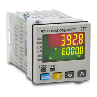
Explains the function of the digital display, status indicators, and control keys.

Model Number Explanation

Provides a breakdown of the CTT Series model numbering system for identification.

General Specifications

Power and Input Specifications

Lists the power requirements and input signal characteristics of the device.

Performance and Timing Specifications

Details the operational performance, accuracy, and timing capabilities.

Environmental and Agency Approvals

Covers operating environment conditions and relevant safety/compliance certifications.

Terminal Layout

CTT-1 C Terminal Configuration

Illustrates the terminal connections for the CTT-1C model.

CTT-AN Terminal Configuration

Illustrates the terminal connections for the CTT-AN model.

CTT-1 C Analog Input Configuration

Shows the terminal layout for CTT-1C models with analog input.

CTT-AN Analog Input Configuration

Shows the terminal layout for CTT-AN models with analog input.

Operation Examples

Counter Example: Counting Up

Demonstrates the procedure for setting up and using the counter for upward counting.

Timer Example: Signal Delay

Illustrates how to configure the timer for a signal delay function.

Tachometer Example: Using PSCAL

Shows how to use the PSCAL parameter for tachometer speed measurement.

Parameter Setup

Keypad Setup for Counter

Guides on setting parameters using the keypad for counter functions.

Keypad Setup for Timer

Guides on setting parameters using the keypad for timer functions.

Keypad Setup for Tachometer

Guides on setting parameters using the keypad for tachometer functions.

Additional Help and Support

Technical Support Information

Provides contact details for technical assistance and additional product information.

Online Resources

Links to the AutomationDirect website for product manuals and video tutorials.

Overview

The CTT Series is a versatile digital counter/timer/tachometer designed for industrial applications, offering a range of functionalities including single-stage counting, two-stage counting, batch counting, total counting, dual counting, timing (up and down), and tachometer operations. This device is powered by 24-240 VAC/DC and operates within a frequency range of 50/60 Hz. It features a compact design with dimensions of 48x48x80mm (1.89x1.89x3.15 inches) and a panel cutout of 45x45mm (1.77x1.77 inches), making it suitable for integration into various control panels.

Function Description:

Counter Mode:

In counter mode, the CTT Series can perform various counting tasks. For single-stage counting, it can be configured to increment a present value (PV) with each leading edge of an input signal at CP1. When the PV reaches a preset count setting value (SV), both outputs 1 and 2 can be activated. A reset input signal at RST1 can turn off outputs, reset the PV to 0, and enable further counting. The device supports counting up, counting down, command counting up/down, individual counting up/down, and quadrature input. It offers multiple output modes (S, T, D) that are valid with specific input modes (Ud_A, Ud_b, Ud_C). Counting speeds can be set up to a maximum of 10 Kcps, with other options including 5K, 1K, 200, 30, and 1 cps. The pulse width of output 1 and output 2 can be adjusted, with a default of 0.02 seconds, or set to 0.00 seconds for continuous output. The decimal point position can be configured from 0 to 3 digits after the decimal point, and a pre-scale value (PSCALE) can be set from 0.001 to 99.999. The device also allows saving or clearing the PV upon power off. The minimum width of the reset signal is 20ms by default, with a 1ms option. Input signal types can be selected as NPN or PNP.

Timer Mode:

The timer function supports both timing up and timing down. It offers various timer modes, including Signal On Delay 1 (Sond1), Signal On Delay 2 (Sond2), Signal Off Delay (SOFFd), Signal On/Off Delay (Sonb), Repeat Pulse On Delay (Pond), Repeat Pulse Off Delay (Pondh), Cycle On Delay (CYH), Cycle Off Delay (CYL), Stop On Delay (Ston), Stop Off Delay (Stoff), and Stop On/Off Delay (Stonb). The display unit can be configured from 10ms to hours. The pulse width of output 1 can be adjusted from 0.02 seconds (default) to 0.00 seconds for continuous output. The minimum width of the reset signal is 20ms (default), with a 1ms option. Input signal types can be selected as NPN or PNP.

Tachometer Mode:

In tachometer mode, the CTT Series can monitor rotational speed and convert pulsed signals from encoders or sensors into engineering units using the PSCALE feature. This is particularly useful for applications such as monitoring motor RPMs. The device offers four output modes: 2Lo1Lo, 2Lo1Hi, 2Hi1Lo, and 2Hi1Hi, allowing for flexible output control based on preset values. Rotation speed can be set up to a maximum of 10 Kcps, with other options including 5K, 1K, 200, 30, and 1 cps. The decimal point position can be configured from 0 to 3 digits after the decimal point. The pre-scale value (PSCALE) can be set from 0.001 to 99.999. A delay time after power-on can be set from 0.1 to 99.9 seconds, after which the tachometer will begin operation. An average value for the input filter can be configured from 0 to 3 (1=2 data, 2=4 data, 3=8 data) to stabilize the displayed present value. The minimum width of the reset signal is 20ms (default), with a 1ms option. Input signal types can be selected as NPN or PNP.

Important Technical Specifications:

  • Power Supply: 24-240 VAC/DC, 50/60 Hz
  • Dimensions: 48x48x80mm (1.89x1.89x3.15 inches)
  • Panel Cutout: 45x45mm (1.77x1.77 inches)
  • Display: 6-digit LED display (Red PV, Green SV)
  • Input Types: NPN/PNP selectable
  • Output Types: Relay (SPDT, 3A @ 250 VAC/30 VDC resistive)
  • Counting Speed: Max. 10 Kcps (selectable options: 5K, 1K, 200, 30, 1 cps)
  • Timing Range: 0.001s to 99999.9h (selectable units: 10ms, 100ms, 1s, 10s, 1min, 10min, 1h, 10h)
  • Tachometer Range: 0.001 to 99999.9 (units: RPM, RPS, Hz, KHz, m/min, m/s, L/min, L/s, m3/min, m3/s)
  • Operating Temperature: -10 to 50°C (14 to 122°F)
  • Storage Temperature: -20 to 60°C (-4 to 140°F)
  • Humidity: 35-85% RH (non-condensing)
  • Insulation Resistance: >100MΩ (500 VDC)
  • Dielectric Strength: 2000 VAC, 50/60 Hz for 1 minute
  • Vibration Resistance: 10-55 Hz, 0.75mm amplitude for 2 hours
  • Shock Resistance: 300m/s² (30G) for 3 times
  • Electrical Noise Immunity: ±2000V 1µs pulse on power supply and input terminals
  • Approvals: CE, UL Listed (E236118)

Usage Features:

The CTT Series offers a user-friendly interface with a 6-digit LED display for clear visibility of both the present value (PV) and the set value (SV). The device is easily configured via its front panel buttons, allowing users to navigate through various parameter settings for counter, timer, and tachometer modes. The quick start guide provides clear instructions for basic setup and operation. The ability to select NPN or PNP input types ensures compatibility with a wide range of sensors and control systems. The flexible output modes and adjustable pulse widths allow for precise control in various applications. The pre-scale function (PSCALE) is a significant feature, enabling conversion of raw pulse signals into meaningful engineering units, which simplifies data interpretation and system integration. The decimal point position can be adjusted to suit the required precision of the displayed values. The device also includes features like power-on delay for tachometer mode and input filter averaging to ensure stable and reliable readings.

Maintenance Features:

The CTT Series is designed for robust industrial environments, with a durable construction that meets CE and UL standards. Its wide operating temperature range and resistance to vibration and shock ensure reliable performance in challenging conditions. The device's electrical noise immunity helps prevent interference from other equipment, contributing to stable operation. While specific maintenance instructions are not extensively detailed in the provided information, the general design suggests a low-maintenance device. Regular checks of wiring connections and ensuring the device operates within its specified environmental conditions would be standard practice to ensure longevity. The clear display and accessible parameter settings facilitate easy troubleshooting and adjustments if needed. The availability of a complete product manual online provides comprehensive information for advanced setup, troubleshooting, and maintenance.

AutomationDirect CTT Series Specifications

General IconGeneral
BrandAutomationDirect
ModelCTT Series
CategoryCash Counter
LanguageEnglish