Gray: Dash Lights. Connect to factory dash lighting wire. Look for a power that turns on and off with the parking lights and or head lights, but
also dims (power lowers) as you adjust your headlight dimmer. A test light works well for checking this. Check pin 29/Gray wire of the factory
cluster connector. If by chance you have a faulty dimming circuit in your vehicle, you can use any of the wires from your headlight switch that
turn on & off with the park lights. The factory dimmer is not used by the InVision Digital Dash. There is more on the functionality of this later in
step 4 of the instructions.
Red (4 foot): 12v, key on power. Connect to the factory gauges power only if it is 12v. This power should turn on and off with the ignition
switch. Check pin 22/Pink wire of the factory cluster connector. If there is no factory wire to use, you might nd an ignition power from the fuse
box, or from the ignition switch. This should be protected with a standard automotive 5A inline fuse.
Pink: Battery power, for memory retention. You should connect this to any constant-on, battery power such as at the factory fuse box, the
ignition switch, or directly to the battery. Check for power at these locations by leaving the key switched off, and using your test light to locate
power that is still on. This should be protected with a standard automotive 3A inline fuse.
Black (4 foot): System ground. We recommend you choose a new ground location for this wire, preferably at the engine. You can ground
to the rear of one of the cylinder heads, or on the intake manifold to one of the unused accessory bolt holes. We do NOT recommend using
existing, factory cluster ground as this is going to be a much older circuit, which may no longer be a very clean ground.
Green w/ red stripe: Hi Beam indicator. Connect to the factory hi beam indicator wire or to the hi beam switch. Check pin 5/Either White, or
Light Green wire of the factory cluster connector. This circuit will be powered only when the headlights are on, and the high beams are on.
Blue w/ white stripe: Left turn indicator. Connect to the factory left turn indicator wire. You can test for this with a test light. Turn the key on,
and then the left turn signal on. Look for the wire that ashes your test light with the turn signal. Check pin 3/Light Blue wire of the factory
cluster connector.
Blue w/ red stripe: Right turn indicator. Connect to the factory right turn indicator wire. You may test for this with a test light Turn the key on,
and then the right turn signal on. Look for the wire that ashes your test light with the turn signal. Check pin 32/Dark Blue wire of the factory
cluster connector.
Red (2 foot): 12v key on power. This is intended for applications where you might be using a 3-wire vehicle speed sensor that requires power.
You should nd that this wire is powered any time that the InVision Digital Dash is powered. You can also use this to power a GPS interface
module, or some other accessory as desired as long as it ts within the recommended fuse requirements. **If running a stock, factory
drivetrain, this wire will not be needed. This is only needed if you are using an after market, non-stock, 3 wire speed sender.
Green w/ white stripe: Temperature sender wire. Run this out to the engine bay, to where you will install the Auto Meter temperature sender.
Violet: Speed signal. Connect this to the signal wire at your speed sender/sensor. If you are using a computer (ECM, PCM, ECU, etc.), you
can connect this to the factory speed signal wire at the computer instead of the speed sensor if it is equipped. Consult a diagram for your
computer to verify.
We recommend connecting to the purple wire with white stripe, at the speed sensor directly, or to the same color wire at the Speed Buffer for
1995 applications (located beneath the ECM behind the right side of the glove box), or the same color wire, pin 30 at the PCM under the hood
on 1996 to 1998 models.
Brown: Oil PSI sender wire. Run this out to the engine bay, to where you will install the Auto Meter oil pressure sender.
Green: Tachometer signal wire. Where you connect this wire will depend on what ignition system you have. If your engine is distributor
equipped, with no ignition box, you can connect to the negative side of the ignition coil. If you are using an aftermarket ignition box, you will
connect the green wire to the dedicated tachometer signal output wire and NOT to the ignition coil. If your application has no distributor or
ignition box and is using coil packs you might have an available tachometer signal at your computer. If you have questions on this, please call
AutoMeter Tech Support at (866)-248-6357. If still using the factory, original engine and ignition system, you may connect to pin 6/white wire
of the factory cluster connector.
Black (2 foot): Speed Sensor/Sender Ground. This is used only if you have a speed sensor/sender that requires a supplied ground. If you
have a speed sensor that is already existing/functioning that is already grounded or is grounded by a computer, then this wire is not needed.
If you need to supply ground to your speed sender/sensor, then connect this black wire to the ground wire of your speed sender/sensor. **If
running a stock, factory drivetrain, this wire will not be needed. This is only needed if you are using an after market, non-stock, speed sender.
Orange: Fuel sender wire. Connect to the original fuel sender wire. GM typically used tan, pink, or violet for this. To be sure, you may use a
You can then remove the Selector Knob from the rear of the InVision Digital Dash by removing the two T10 Torx or phillips head screws. Now
you can
move the InVision Digital Dash out of the way so that you have plenty of room to work.
Wiring will require some basic automotive electrical knowledge, and in some cases a vehicle specic wiring diagram, or the ability to test
circuits to verify proper hook ups. You will need to be able to test various circuits at this time. You will nd the following wire colors on your
new InVision Digital Dash. There are several different methods of connection that you can use when connecting the InVision Digital Dash wire
harness to your existing wiring:
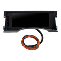
Step 2, Wiring:
Although the InVision Digital Dash comes assembled, the wiring will take a little time, therefore it is easier to disconnect the wire harness from
the rear of the InVision Digital Dash. Push down on the blue locking tab, so that you can pull the pink latch all the way up, and over as shown
in the pictures below. The connector will then easily pull out. When you are ready to reinstall the wire harness, follow the steps in reverse
order, except that you won’t have to push the locking tab to install (you will need to secure the pink latch).
 Loading...