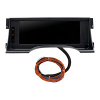
The InVision dash comes with 3 external warning indicator lights that are option for you to wire up and use, to
keep factory systems functioning properly. They are charging system, ABS brakes, and Air Bag (SIR). Each of
these use a common 194 bulb. Top is Charging Light, Middle is ABS Light, Bottom is Air Bag Light.
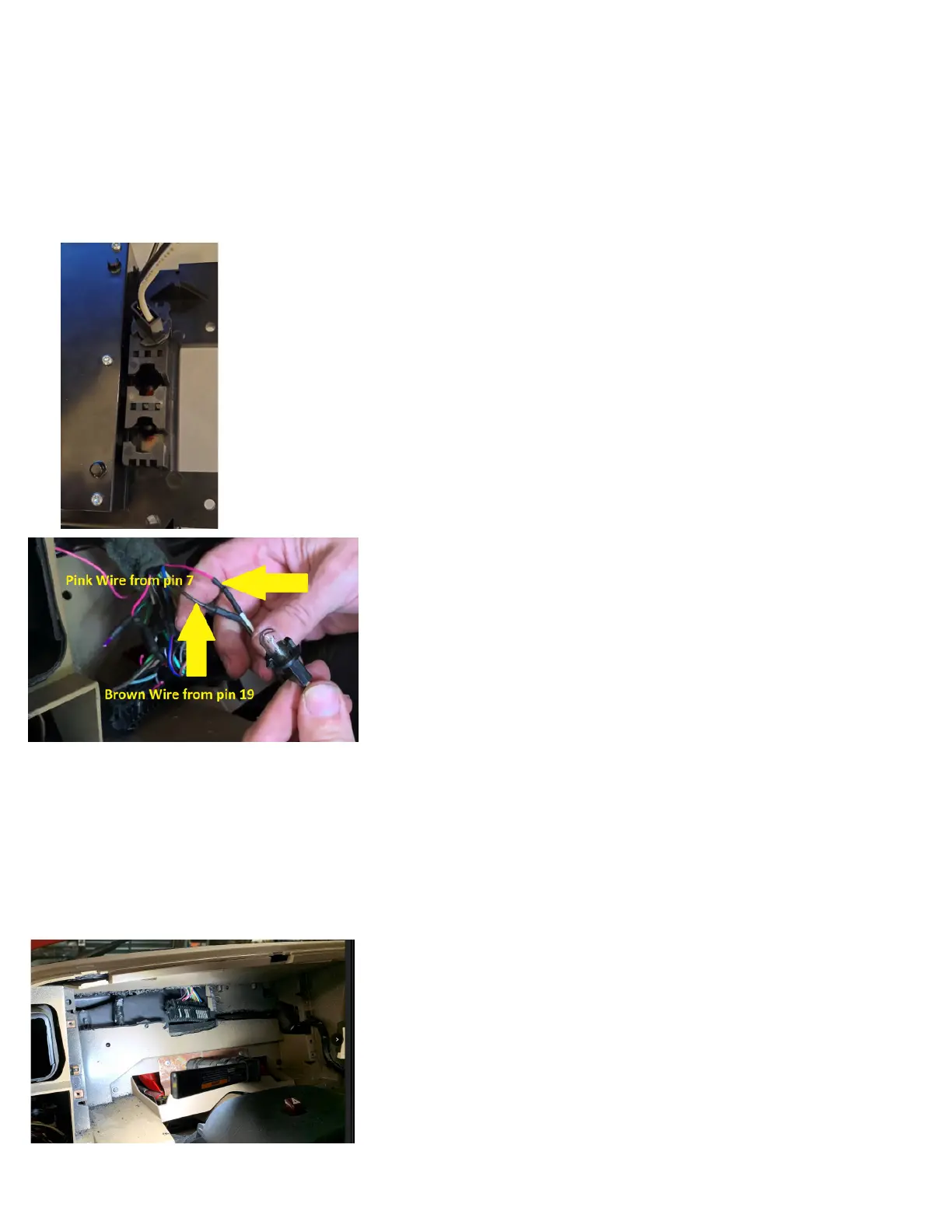
To wire up the charging system warning light (required for the factory charging system to function properly),
you will locate the Brown wire at pin 19 of the factory cluster connector, and connect either of the supplied
bulb socket wires to this. Next, wire the 2nd wire of the supplied bulb socket to the pink wire at pin 7 of the
factory cluster connector (keep in mind when wiring this, you may share this same pink wire for the other
two bulb sockets). When wired correctly, the bulb you just wired in will turn on when you turn the key to the
RUN position, and as soon as you start the engine, the bulb will go out as long as the charging system is
functioning.
Now is a good time to plug your harness into the new dash display, and turn power on to
make sure all of your wiring is good, and to become familiar with the dash. Remember
you still have senders to connect outside of the interior at this point. We will cover Set Up
details later, though for now, simply make sure that your dash powers up, and that turn
signals, and hi beam indicator (when lights are on) function.
Before you can install the dash permanently, you will have to cut a portion of the rear
plastic wall out, from behind where the original cluster was. You will have to cut the raised
portion out that secured the original cluster connector. You will then cut a trail down, and
to the right, in order to have clearance for the selector knob.
Lastly, you will want to cut out the area to the left as well, and up, in order to have room
to stuff any extra harness length during the nal install. *Be careful how deep you cut, as
there are other items behind that plastic wall.
digital ohm meter to test which wire is correct. To determine the correct wire, set your ohm meter to its lowest setting (most commonly 200, with
no K or M sufx). Connect the positive lead of the meter to the wire you are going to test. Ground the meters negative lead. You are looking for
something that resembles the fuel level reading you had before removing the original dash. For example, if the factory sender is 0 to 90 ohms.
If the tank was at or near E, you might see 0 to 4 ohms. If the tank was at half tank, the reading should be about 45 ohms. If the tank was at
Full, the reading should be near 90 ohms. The fuel level sender simply varies from 0 to 90 based on the amount of fuel there is in the tank. If the
factory fuel gauge did NOT function, you may have further diagnosis to do to test the sender in the tank, the sender ground, and the sender wire
itself. Call AutoMeter Tech Support at (866)-248-6357 if further assistance is needed. Check pin 16/Purple wire of the factory cluster connector.
Brown w/ white stripe: Service Engine Soon Indicator. Not all applications will use this. This is only used if you are using an engine management
system that has a grounded output for a Service Engine Soon light. If still using the factory, original engine and engine management system, you
may connect to pin 23/Brown with White Stripe wire of the factory cluster connector.
Six pin connector. For future expansion. ***See Image on page 13.
Next, if equipped, you may now wire in the ABS warning light. Again, this is required if your truck is equipped with ABS brakes, and you still want
them active. Locate the Lt Green wire at pin 27 of the factory cluster connector, and connect either of the supplied bulb socket wires to this.
Next, wire the 2nd wire of the supplied bulb socket to the pink wire at pin 7 of the factory cluster connector (keep in mind when wiring this, you
may share this same pink wire for the other two bulb sockets). When functioning correctly (with no ABS faults), the bulb should illuminate for
about 2 seconds with every power up, then go out.
Next, if equipped, you may now wire in the Air Bag/SIR warning light. Again, this is required if your truck is equipped with a functioning air bag.
Locate the Brown wire at pin 1 of the factory cluster connector, and connect either of the supplied bulb socket wires to this. Next, wire the 2nd
wire of the supplied bulb socket to the pink wire at pin 7 of the factory cluster connector (keep in mind when wiring this, you may share this same
pink wire for the other two bulb sockets). When functioning correctly (with no Air Bag faults), the bulb should illuminate & ash several times (up
to 7) with every power up, then go out.
Once this is clearanced, you can install your new instrument cluster, and secure it with the original screws that you removed earlier.
Next, get your original instrument cluster bezel into position, plug in anything that had to be unplugged during disassembly, and then carefully
line it up, and snap it back into place.
Picture is example of wiring Charging light.
 Loading...