ZONE 1
ZONE 4 ZONE 5 ZONE 6
ZONE 2 ZONE 3
Expansion
Toslink
ZONE 7 ZONE 8
IR OUTPUTS
M-800
MIRAGE 8-ROOM
DIGITAL AMPLIFIER
1st Amp
ZONE 1
ZONE 4 ZONE 5 ZONE 6
ZONE 2 ZONE 3
Expansion
Toslink
ZONE 7 ZONE 8
IR OUTPUTS
M-800
MIRAGE 8-ROOM
DIGITAL AMPLIFIER
2nd Amp
Subsequent M-800 or M-400 Amps
If the system contains multiple
Mirage ampliers, attach a standard
straight-through CAT5 cable from
the upper Expansion Port on the rst
amplier to the lower Expansion Port
on the subsequent amplier.
Additionally, for each source attach
a coax RCA cable from the sources
digital output on the rst amplier to
the digital input on the next amplier
in the chain and so forth. Repeat for
each amplier in the chain.
ZONE 1
ZONE 4 ZONE 5 ZONE 6
ZONE 2 ZONE 3
Expansion
Toslink
ZONE 7 ZONE 8
IR OUTPUTS
M-800
MIRAGE 8-ROOM
DIGITAL AMPLIFIER
Mirage Amplier
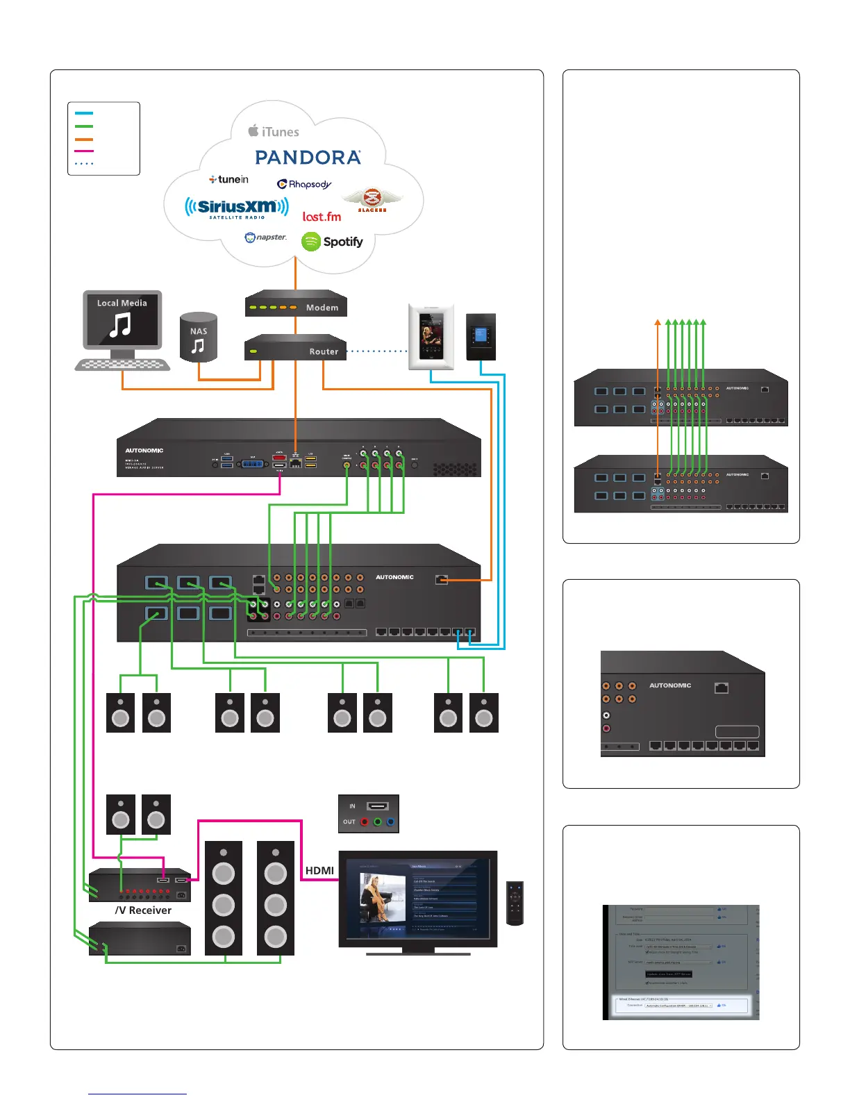
Mirage Media Server (MMS-5A Displayed in this diagram)
(M-800 Displayed in this diagram)
Kitchen
(Mac or PC)
Living Room
Main Room
HDMI
HDMI
A/V Receiver
Bedroom
Component Video
Patio
An HDMI-to-component
adapter is required to
connect component-based
video (not included)
KP-iOS KP-1
Power
Audio
LAN
HDMI
Wi-Fi
2-Channel Amp On-Screen Navigation (OSN) with IR Remote
(IR Remote included with MMS-5A only)
Listening Room
Typical System Conguration
Stacking Amps
How to ID Multiple Amps in a Stack
How to ID a MMS MAC Address
Note: The M-400 Amplier does not have Pre-Amp Outputs.
(g. 4)
(g. 5)
(g. 7)
(g. 6)
The MAC address of the amp can
be found printed on the back of
the unit in the lower right corner.
The MAC address of the server can
be found on the Server Settings tab
of the server’s web conguration
listed next to ‘Wired Ethernet’.
ZONE 1
ZONE 4 ZONE 5 ZONE 6
ZONE 2 ZONE 3
Expansion
Toslink
M-800
MIRAGE 8-ROOM
DIGITAL AMPLIFIER
Mac Address