EasyManua.ls Logo

Autopilot APCEM2 User Manual

Autopilot APCEM2
9 pages
To Next Page IconTo Next Page
Page #1 background imageLoading...
Page #1 background image
Troubleshooting Autopilot Controllers
PLEASE READ ENTIRE INSTRUCTIONS (FOR YOUR SPECIFIC CONTROLLER) BEFORE
ATTEMPTING TO TROUBLESHOOT. JUMPING AHEAD WILL RESULT IN IMPROPER TESTING.
Summary of features and applications:
APCECOTH: Controls temp, humidity, and CO2 with digital accuracy, as well as an outlet that comes on during
Lights Off (Night output). Ideal for sealed rooms with air cooled lights and an AC unit, although has settings to
work with non-sealed rooms as well.
APCETHD: Controls temp and humidity with digital accuracy. The CO2 outlet is a recycle timer, so the proper
on and off times must be calculated dependent on room size etc. Ideal for sealed rooms with air cooled lights
and an AC unit, although has settings to work with non-sealed rooms as well.
APCETHA: Controls temp and humidity with the accuracy of a knob (less than digital). The CO2 outlet comes
on whenever the grow lights are on, and the Cooling outlet is not on. Ideal for non-sealed room, with an
exhaust fan controlling temp, although can work with sealed rooms as well.
APCET
: Analog thermostat, with separate Day and Night temp setting knobs.
APCECOD: Controls CO2 with digital accuracy. More customizable CO2 control than the APCECOTH, including
the capability of increasing or decreasing CO2. Ideal for a sealed room that already has a controlled
environment (temp/humidity), although will work with a non-sealed room as well.
APCECO: Analog version of the APCECOD. Current CO2 level displayed via blinking lights.
APCTMDT: Controls lights with an internal clock, has a recycle timer, and a High Temp Shutoff, all controlled
with digital accuracy. Night output comes on when lights are off.
APCTART: Analog Recycle timer, separate ON and OFF time knobs. For example, use for controlling a pump to
come on for 5 minutes every 30 min, or 30 seconds every 10 minutes, etc. No internal clock, turns on and off
based on the ON/OFF time settings, and whether on Daytime mode, Nighttime mode, or 24 hour mode.
Question and Answer IconNeed help?

Do you have a question about the Autopilot APCEM2 and is the answer not in the manual?

Autopilot APCEM2 Specifications

General IconGeneral
Output Current10 A
Current Rating10 A
Operating Frequency50/60 Hz
ProtectionOverload, Short Circuit
CertificationCE

Summary

Troubleshooting Digital Autopilot Controllers

Screen and Display Checks

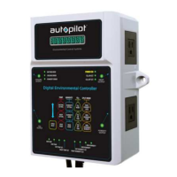
Verify LED screen startup sequence and check for display dead spots.

Button and Input Testing

Test functionality of all buttons, including arrow keys, on the controller.

Photocell Sensor Functionality

Check photocell operation by covering it; the DAYTIME MODE LED should turn OFF.

Environmental Sensor Accuracy

Verify Temp, Humidity, and CO2 readings against calibrated monitors and outdoor air.

Timer and Clock Operation

Test the internal clock and cycle timer settings for accuracy and operation.

Outlet and Relay Testing

Verify power output from each controller outlet by plugging in small devices.

Digital Autopilot Controller Error Codes

Memory Chip Errors

"Err.EEP" indicates a problem with the memory chip. Return unit and sensor.

Temperature Sensor Errors

"Err.tMP" or "Err.tEP" indicate temp sensor issues. Check connection.

Humidity Sensor Errors

"Err.Hul" indicates a humidity sensor problem. Check connection.

General Sensor Probe Errors

"Err.SEn" indicates a sensor probe issue. Check connection.

Photocell Sensor Errors

"Err.Lig" indicates a photocell sensor fault. Return unit and sensor.

Real-Time Clock Errors

"Err.rtc" indicates a real-time clock error (APCTMDT only).

Troubleshooting Analog CO2 Controller APCECO

Initial Setup and Photocell Test

Plug in, set knobs, and test photocell for DAYTIME light.

CO2 PPM Level Testing and Calibration

Test CO2 readings by counting lights and calibrate if needed.

Relay Output Test

Test the relay by setting SET POINT to 2500 ppm and checking the RELAY ON light.

Troubleshooting Analog Temp Controller APCET

Initial Setup and Photocell Test

Plug in, ensure proper placement, and test photocell operation.

Relay and Output Testing

Test the relay by adjusting the SET DAY knob and verifying outlet power.

Temperature Sensor Accuracy

Test temperature sensor by adjusting SET DAY knob until output light turns off/on.

Analog Temp Controller Error Codes

Understand error codes like Abnormal Temperature and Max Amperage Exceeded.

Troubleshooting Analog Temp/RH Controller APCETHA

Photocell and Night Output Test

Test photocell; DAYTIME MODE LED should turn OFF and NIGHT OUTPUT should come on.

Temperature Sensor Verification

Test temperature sensor by turning knob until Cooling output light turns off/on.

Humidity Sensor Verification

Test humidity sensor by turning knob until Humidity output light turns off/on.

Relay and CO2 Output Testing

Test Cooling, Humidity, and CO2 outputs by adjusting knobs and covering photocell.

Method Selection Button Test

Test the "Select Method" button to cycle through Methods 1, 2, and 3.

Troubleshooting Analog Cycle Timer APCTART

Initial Setup and Photocell Test

Plug in, ensure proper placement, and test photocell; DAYTIME MODE LED should turn OFF.

Cycle Time and Relay Verification

Test cycle timer and relay by setting knobs to 15 sec and verifying output.

Mode Selection and Accuracy

Set DAY/NIGHT/24 HR modes and use stopwatch for accurate timing.

Analog Cycle Timer Error Codes

Understand error codes like Max. Amperage Exceeded for the timer.

Related product manuals