Ο∆ΗΓΙΕΣ ΕΓΚΑΤΑΣΤΑΣΗΣ ΚΑΙ ΠΡΟΓΡΑΜΜΑΤΙΣΜΟΥ ΠΙΝΑΚΑ R2010-D 230 Vac
INSTALLATION AND PROGRAMMING MANUAL FOR CONTROL BOARD R2010-D 230 Vac
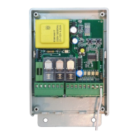
TRIMER
DSW
LD1 LD2 LD3 LD4
RC
LD5
M1 M2
F1
MCU
K1
K2
TR
BT
4321
ON
ΠΡΟΕΙ∆ΟΠΟΙΗΣΗ - ΕΓΚΑΤΑΣΤΑΣΗ
Το προϊόν πρέπει να εγκατασταθεί από εξειδικευµένο
προσωπικό, το οποίο µπορεί να πραγµατοποιεί τις εργασίες εγκατάστασης αυστηρά σύµφωνα µε τους κανόνες ασφαλείας. Το προϊόν δεν πρέπει να
χρησιµοποιείται λανθασµένα ή για οποιουσδήποτε άλλο σκοπό για τόν οποίο δεν έχει σχεδιαστεί. Πριν προχωρήσετε µε την εγκατάσταση είναι
απαραίτητο να διαβάσετε προσεκτικά τις οδηγίες χρήσης για να αποφύγετε τους κινδύνους για τους χρήστες ή καταστροφή του εξοπλισµού. Είναι
απαραίτητο για να τροφοδοτήσετε τον εξοπλισµό να χρησιµοποιήσετε 6Α/30mA διαφορικό ρελέ διαρροής. Πριν από κάθε εγκατάσταση ή εργασίες
συντήρησης απενεργοποιήστε την παροχή ρεύµατος προς τη συσκευή µε το διπολικό διακόπτη. Ο εξοπλισµός δεν πρέπει να αλλοιωθεί ή τροποποιηθεί µε
οποιονδήποτε τρόπο. Είναι απαραίτητο να απενεργοποιήσετε την παροχή ρεύµατος στον εξοπλισµό πριν από την εγκατάσταση ή το άνοιγµα του κουτιού.
Ο κατασκευαστής διατηρεί το δικαίωµα να κάνει αλλαγές στο προϊόν χωρίς προειδοποίηση. Ως εκ τούτου αυτό το εγχειρίδιο µπορεί να µην αντιστοιχούν
ακριβώς στις προδιαγραφές του προϊόντος.
Πριν την πραγµατοποίηση των ηλεκτρικών συνδέσεων, είναι απαραίτητο να απενεργοποιήσετε το δίκτυο των 230V 50Hz.
2
Χρησιµοποιήστε καλώδια µε διατοµή 0,5mm για να κάνετε τις συνδέσεις µε τα µπουτόν, τα φωτοκύτταρα και την παροχή ρεύµατος 24V. Για συνδέσεις της
2
παροχής ρεύµατος 230V 50Hz και του κινητήρα, είναι αναγκαίο να χρησιµοποιήσετε καλώδια µε διατοµή τουλάχιστον 1,5mm . Είναι απαραίτητο να
τοποθετήσετε και να βιδώσετε σφιχτά τα καλώδια των σηµάτων στην κλέµµα Μ2 και τα καλώδια ισχύος στην κλέµµα M1 ξεχωριστά. Μην συνδέετε άλλα
εξαρτήµατα σε οποιαδήποτε είσοδο της κλέµµας, εκτός από εκείνες για τις οποίες έχουν σχεδιαστεί.
ATTENTION-INSTALLATION
The Product must be installed by
qualified personnel who can carry out the installation operation strictly in compliance with safety rules. The device must not be used
incorrectly or for any purposes other than the ones designed for. Before proceeding with the installation it is necessary to read the
instruction manual carefully in order to avoid danger to either the users or the equipment. It is necessary to power the device using a 6A
bipolar thermomagnetic switch equipped with a differential with an operating current of 0.03 A. Before currying out any installation or
maintenance operations turn off the power supply to the device with the bipolar switch. The equipment must not be tampered with or
modified in any way. it is necessary to turn off the power supply to the equipment before installing it or opening the enclosure.
The manufacturer reserves the right to make changes to the product without prior notice. Therefore this manual may not
correspond exactly to the product specifications.
Prior to the electric connection shut down the 230V 50Hz power supply.
2
Use 0,5mm to connect the buttons, photocells and 24V power supply. For 230V 50Hz connections and motor connections use at least
2
1,5mm cables.
It is very important to firmly tight the signal cables of terminal Μ2 and power cables on terminal M1 separately to avoid
errors. Do not connect any kind of device in the terminal inputs other than the one they are designed for.
Ο ηλεκτρονικός πίνακας R2010-D είναι κατάλληλος για τον έλεγχο µονοφασικών ηλεκτροκινητήρων µε ενσωµατωµένους ή
εξωτερικούς τερµατικούς διακόπτες. Η µέγιστη κατανάλωση του κινητήρα που µπορεί να συνδεθεί είναι 650 W στα 230Vac 50Hz. Ο
προγραµµατισµός των παραµέτρων πρέπει να πραγµατοποιείται µετά την εγκατάσταση του συνόλου του εξοπλισµού.
R2010-D control board is suitable for 230VAC one actuator with built in or external limit switch.
The max absorption of the device is 650 W per 230Vac 50Hz.
The setup of the parameters must be carried out after the installation of all the aquipment.
ΠΕΡΙΓΡΑΦΗ
TRIMMER =
DSW =
LD1 - LD4 =
LD5 =
F1 =
M1 =
M2 =
RC =
K1 - K2 =
TR =
MCU =
BT =
ΕΠΑΦΕΣ Μ1
GND =
L =
N =
OPEN =
CLOSE =
ΕΠΑΦΕΣ Μ2
~24V =
COMMON =
OPEN =
CLOSE =
START =
PHOTO =
COMMON =
ANT =
Ρυθµιστικό trimmer προγραµµατισµου αυτόµατου κλεισίµατος
Μικροδιακόπτης Dip Switch
Ενδεικτικά LED εισόδων
Ενδεικτικό LED προγραµµατισµού
Ασφάλεια 230Vac
Κλέµα εισόδων – εξόδων τάσης 230Vac
Κλέµα εισόδων – εξόδων χαµηλής τάσης
∆έκτης
Ρελέ
Μετασχηµατιστής
Μικροεπεξεργαστής
Μπουτόν προγραµµατισµού τηλεχειριστήριων
Είσοδος γείωσης
Είσοδος φάσης 230V 50Hz
Είσοδος ουδετέρου 230V/50Hz
Άνοιγµα κινητήρα
Κλείσιµο κινητήρα
Εξοδος 24v για τροφοδοσία φωτοκυττάρου
Κοινό εισόδων
1. Είσοδος τερµατικου διακοπτη N.C. Ανοιγµατος (για µοτέρ µε εξωτερικα τερµατικά)
2. Είσοδος µπουτόν N.O. εντολής ανοίγµατος Dead Man (για λειτουργία µοτέρ µε
ενσωµατωµένα τερµατικά)
1. Είσοδος τερµατικου διακοπτη N.C. κλεισίµατος (για µοτέρ µε εξωτερικα τερµατικά)
2. Είσοδος µπουτόν N.O. εντολής κλεισίµατος Dead Man (για λειτουργία µοτέρ µε
ενσωµατωµένα τερµατικά)
Είσοδος µπουτόν N.O. (Άνοιγµα / Κλείσιµο)
Είσοδος εντολής φωτοκύτταρου N.C.
Κοινό εισόδων.
Εισοδος κεραίας δέκτη τηλεχειρισµου
DESCRIPTION
TRIMMER =
DSW =
LD1 - LD4 =
LD5 =
F1 = Fuse
M1 = Input / output terminal
M2 =
RC =
K1 - K2 =
TR =
MCU =
BT = Remote control programming button
TERMINAL Μ1
GND =
L = Line input
N =
OPEN =
CLOSE = Motor close
TERMINAL Μ2
~24V = V output for photocell power supply
COMMON = Input common
OPEN =
CLOSE =
START = Button input (OPEN / CLOSE )
PHOTO =
COMMON =
ANT =
Auto close setting trimmer
Dip Switch
Input LEDs
Programming LED
230Vac
230Vac
Low voltage Input / output terminal
Receiver
Rellay
Transformer
Micro control unit
Ground input
230V 50Hz
230V/50Hz Neutral inout
Motor open
COM = Common
24
1. Limit Switch Input N.C. OPEN (for external limit switch)
2. Button Input N.O. Open Command Dead Man (for built in limit switch)
1. Limit Switch Input N.C. CLOSE (for external limit switch)
2. Button Input N.O. Close Command Dead Man (for built in limit switch)
Photocell command input N.C.
Input common
Antenna input
1999/5/EC
EN60950
EN301489-1
EN301489-3
EN300220-3
Radio & Telecommunications Terminal Equipment directive
AUTOTECH - G .KAPSALIS
8, Archimidous str. 12134 Peristeri Athens,
Greece, Tel: +302105780019, Fax: +302105785112
In accordance with the following directives:
DECLARATION OF CONFORMITY
hereby declare that:
Product : S5070 Electronic Control Board for Opening Doors
Model : R2010D
is in conformity with the applicable
requirements of the following documents.
I hereby declare that the equipment named above has been
designed to comply with the relevant sections of the above
referenced specifications. The unit complies with all the
applicable essential requirements of the directives mentioned.
Name: Apergis Antonios
Position: Technical Director
Peristeri, 28 November 2013