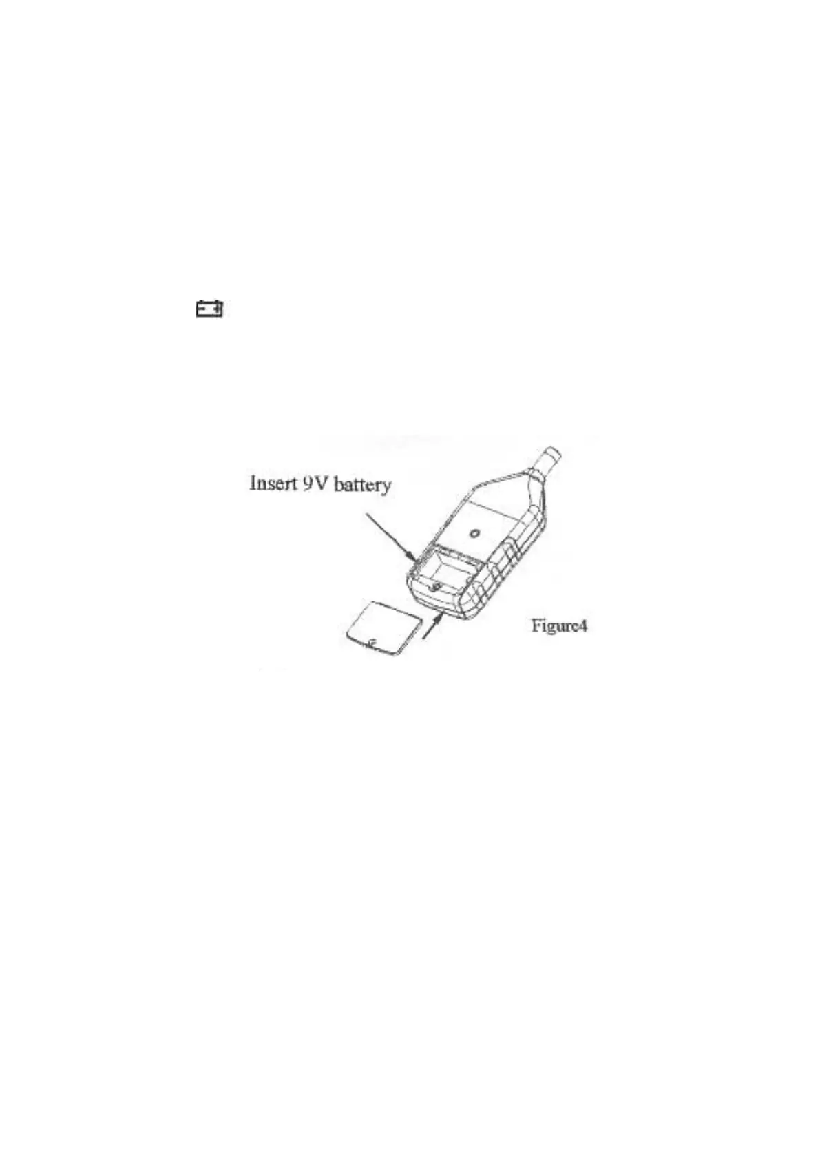
EasyManua.ls Logo

AutoTest Digital Sound Level Meter User Manual

AutoTest Digital Sound Level Meter
8 pages
To Next Page IconTo Next Page
To Previous Page IconTo Previous Page
Page #6 background image
G. Pre-operation:
1) Use a Screwdriver to open the battery door and install four 9V
battery in the battery compartment.
2) Install battery door with Screwdriver.
3) When the battery voltage drops below the operating voltage, a
symbol appears, please replaced with a new one.
4) When the DC adapter is used, insert the plugs (3.5) of the
adapter into the DC 9V connector on the side panel.
H. Operation:
1) Turn on power
2) Select the desired response and weighting, also select desired
range.
3) If weighting for general noise sound level, please select dBA.
4) If the sound source consists of short bursts, set response to FAST.
To measure the average sound level, use the SLOW setting.
5) When the MAX mode is chosen the instrument will capture and
hold the maximum noise level.
- 6 -
Question and Answer IconNeed help?

Do you have a question about the AutoTest Digital Sound Level Meter and is the answer not in the manual?

AutoTest Digital Sound Level Meter Specifications

General IconGeneral
BrandAutoTest
ModelDigital Sound Level Meter
CategoryMeasuring Instruments
LanguageEnglish

Summary

Sound Level Meter Features

Design Standards and Measurement Modes

Complies with IEC651/ANSI S1.4, offers instantaneous measurement, A/C weighting, and Fast/Slow modes.

Measurement Range and Outputs

Covers 30-130 dB range and provides AC/DC signal outputs for analyzers.

Sound Level Meter Specifications

Accuracy, Frequency, and Linearity

Details accuracy (±1.5 dB), frequency range (31.5KHz-8.5KHz), and linearity (50dB).

Measuring Levels and Display

Specifies measuring levels (30-130 dBA/dBC), digital display (5 digits), resolution (0.1dB), and bar graph.

Level Ranges and Indicators

Lists selectable level ranges (e.g., 30-80 dB) and over/under range indicators.

Output Specifications and Components

Defines AC/DC output specs and lists microphone type and power supply.

Calibration Procedures

Calibration Process and Recalibration

Instructions for using an acoustic calibrator and the recommended annual recalibration period.

Name and Functions of Controls

Key Components Identification

Identifies the microphone, LCD display, power switch, and battery door.

Measurement Control Switches

Details level range, MAX hold, frequency weighting (A/C), and time weighting (Fast/Slow) switches.

Output Terminals and Calibration

Identifies AC/DC output terminals and the calibration control.

Mounting and Accessories

Identifies the tripod mounting screw and windscreen.

LCD Display Description

Main Measurement Readouts

Describes display of level range, instantaneous value, measured value, and unit.

Status and Mode Indicators

Explains low battery, MAX hold, over/under range, frequency/time weighting indicators.

Graphical Indicator

Describes the level range bar graph.

Pre-operation Procedures

Battery and Power Setup

Covers battery installation, low battery warning, and DC adapter connection.

Operation Guide

Basic Operation Steps

Includes powering on and selecting response, weighting, and range.

Optimizing for Noise Types

Guidance on using FAST for bursts and SLOW for average levels.

Maximum Value Measurement

Explains using the MAX mode to capture and hold peak sound levels.

Usage Cautions and Environmental Limits

Environmental and Usage Guidelines

Specifies operating temperature/humidity limits and warns against wind noise.

Storage and Battery Handling

Recommends removing batteries for long periods of non-use.