INSTRUCTION
THE AV-201 and AV-601 POWER&SWR meter is the most efficient tool in wide range of semi-professional Measuring And
control instruments. the measured values can be easily read in the large scale instruments.
The AV-201 and AV-601 or is an insertion type RF wattmeter and can be permanently fitted into a transmission System for
continuous monitoring of station working condition .
The unit can be work without external power supply . but with 13.8DC power which permits to light up the Meter and shows
the active led corresponding to the selected RF coaxial line ( for AV-601 )
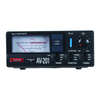
DESCRIPTION OF CONTROL
1 POWER/SWR reading meter 14 led sensor 1
2 Indicator adjustment 15 led sensor 2 (BANK2 ,BANK3 ,BANK4)
3 Power range switch 16 sensor1/sensor2 switch
4 Function switch
5 FWD /REFLECT POWER/OFF SWITCH REMARK :FIG1/FIG2 FOR AV-200/AV-400/AV-201
6 SWR calibration potential-meter :FIG3/FIG4 FOR AV-601
7 Average pep to pep switch
8 200W/1KW select switch
9-12 Antenna connector(connect to the antenna with 50 ohm coaxial cable)
10-13 TX connector (connect to the radio with 50 ohm coaxial cable)
11 Power jack (13.8VDC) light up the meter and sensor 1 / sensor 2 led
FIG1 FIG2
1 7 6 9 10
8
11
2 3 4 5
1 15 14 7 6 12 16 9
8
2 3 4 5 13 11 10
FIG3 FIG4