Apr-09 37
Avantes www.avantes.com info@avantes.com
2.10 Spectrometer Connections
2.10.1 USB1 platform connections
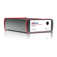
Power LED green and scan LED yellow
The green and yellow LED´s act as status LED´s for the micro controller with following meaning:
Green LED = off, power is not connected
Green LED = on, power is on, micro controller ready, no errors
Green LED = blinking, permanent error detected by micro controller
Yellow LED = on, when scan is transmitted to PC
Power connector
The power connector is a Low power DC connector with GND on outer contact and +12V on inner
contact. The outside diameter is 5.5mm, the inside diameter 2.1mm.
The electrical circuit is protected against reverse polarity and accepts voltages between 8 and 15V.
Power switch (-SPU version only)
Manual switch for power selection for the AvaSpec-SPU
Left external power 12VDC, connect external power supply PS-12V/1.0A
Middle - OFF
Right Power taken from USB bus, no additional power supply required
RS-232 connector
The RS232 interface has the following physical characteristics:
1 start bit, 8 data bits, 1 stop bit
baud rate 115200 bps
flow control with RTS/CTS
female 9 pole Sub-D connector
Power Switch (-SPU version only)
12 VDC OFF - USB power
 Loading...