Do you have a question about the Avanti P180 and is the answer not in the manual?
Instructions for moving the airplane on the ground using a nosewheel towing bar and safety precautions.
Overview of the annunciator panel for ground crew servicing, including switches and warning lights.
Steps for refueling using the gravity filler neck, including switch operations and checks.
Steps for pressure refueling, including nozzle requirements, switch operations, and flow control.
Notes on defueling procedures and restrictions, advising consultation with flight crew.
Guidance on consulting flight crew for correct engine oil type.
Procedure for charging the oxygen system using a filler valve and breathing oxygen bottle.
Specifications for external power units and location of the receptacle.
Guidelines for protecting the airplane, parking in a hangar or moored, and securing it.
Procedure for installing the control lock using a rod and pins.
Instructions for applying and releasing the parking brakes.
Methods for removing ice, snow, and frost using deicing fluids and precautions.
Specifications for tire types and required nitrogen inflation pressures.
Procedures for cleaning windshields and windows, including precautions and rain repellent application.
Steps for cleaning airplane exterior surfaces, including static prevention and fluid application.
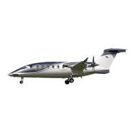
The Avanti P180 is an aircraft designed for efficient ground handling, refueling, and maintenance operations. Its design incorporates features that facilitate ease of movement, comprehensive system checks, and straightforward servicing procedures.
The primary function of the Avanti P180, as described in the manual, revolves around its operational readiness and ease of maintenance on the ground. This includes provisions for towing, a sophisticated ground test/refueling annunciator panel for system monitoring, and various refueling methods. The aircraft is equipped with systems for engine oil management, oxygen supply, and external power connection, all designed for ground crew interaction. Furthermore, it includes features for parking, mooring, control locking, and brake application, ensuring safety and stability when the aircraft is stationary. The design also considers airframe and windshield anti-icing, tire maintenance, and general exterior cleaning, all contributing to the aircraft's overall functionality and longevity.
For ground movement, the Avanti P180 utilizes a nosewheel towing bar. A key operational step is to disengage the steering link connecting pin before towing and to release the parking brake. It is explicitly cautioned not to push or pull on propellers or control surfaces during ground movement to prevent damage. After towing, the steering link should be reconnected, though it may be disengaged while the aircraft is hangared.
The aircraft features a ground test/refueling annunciator panel, accessible via a side-hinged door on the right side of the fuselage under the wing. This panel is crucial for ground crew servicing. It includes a GROUND TEST switch with three positions: LAMP, SYST, and OFF (center). The LAMP position tests all panel lights, ensuring they illuminate. The SYST position tests the monitoring system circuitry, causing all lights to illuminate briefly before turning off, confirming system functionality. The panel also features a REFUEL control switch with OPEN and CLOSED positions. In the OPEN position, the switch opens the left and right fuel systems interconnect valve, enabling single-point gravity or pressure refueling. An amber light (TK INTCON INT) momentarily illuminates, then extinguishes as the valve fully opens, at which point the TANK INTCON amber light comes on. Conversely, in the CLOSED position, the TANK INTCON light goes off, and the TK INTCON INT light momentarily illuminates until the valve is completely closed. It is critical that the fuel systems interconnect valve is open only for refueling operations and closed afterward.
Refueling can be performed via two methods: gravity refueling and pressure refueling. For gravity refueling, the REFUEL switch is set to OPEN, the TANK INTCON annunciator light is verified to be on, the filler cap is removed, and fuel is added through the filler neck. After filling, the cap is reinstalled, and the REFUEL switch is set to CLOSED, ensuring both TK INTCON INT and TANK INTCON annunciators are off. Pressure refueling also begins by opening the REFUEL switch and verifying the TANK INTCON light. The refueling access door is opened, the adapter cap removed, and the nozzle connected. Once refueling pressure is applied, the GROUND TEST switch is set to SYST to verify fuel flow stop. After releasing the GROUND TEST switch, fuel flow continues until the desired level. Upon completion, the nozzle is disconnected, the adapter cap installed, the access door closed, and the REFUEL switch set to CLOSED, again ensuring both TK INTCON INT and TANK INTCON annunciators are off. Defueling is not a standard procedure and requires special consultation with the flight crew, with a specific caution against defueling through the pressure refuel adapter.
Engine oil levels can be checked using the L and R ENG OIL red warning lights on the ground test/refueling panel. These lights illuminate when the oil level is two quarts low. If the lights are off, the GROUND TEST switch should be moved to LAMP, then to SYST, to confirm system functionality and satisfactory oil level. To top off oil, the engine nacelle access door is opened, the filler cap and indicator assembly removed, and oil added to the normal level.
The oxygen system is recharged via a filler valve located on the cabin floor step, aft of the lower cabin door. After removing the protective cap, an aviator's breathing oxygen bottle fitting is attached, the cylinder supply valve opened, and the system slowly filled by adjusting the pressure regulating valve on the bottle. Once the cylinder pressure reaches the specified level, the regulating valve is closed, and the protective cap replaced.
External power can be connected via a receptacle on the left side of the fuselage below the wing. A caution is issued to avoid approaching the aircraft from the rear when connecting or disconnecting external power.
For parking and mooring, the aircraft should be protected from adverse weather by installing dust covers on engine air inlets and exhaust ports, attaching propeller restrainers, and installing pitot covers. For longer periods or overnight, it should be hangared or securely moored, headed into the wind, with flaps retracted. Control gust locks should be installed, main wheels chocked, and tie-down ropes secured to bolt attachment fittings (found in the loose equipment bag) on the underside of the wings.
Control locks are installed by connecting a rod between the pilot control column and rudder pedals. The long pin of the rod is inserted through the pedals locking hole with pedals neutral, and the short pin through the control column locking plate. A pin is then inserted through the hole in the rear side of the pilot's control wheel (when centered), and a clamp positioned around the engine control levers.
Parking brakes are applied by pumping the toe brakes until firm, pulling the parking brake handle, and rotating it 90° clockwise to lock. To release, the handle is rotated 90° counter-clockwise and pushed in completely.
Airframe deicing uses a water/glycol mixture. High-pressure spray is to be avoided to prevent damage to composite surfaces, and deicing fluids should be applied at low angles. Heated deicing fluid or hot water should not be sprayed directly on cold windows but allowed to run down from above. Care must be taken to prevent deicing fluid from entering engines, scoops, or drains, and to ensure ice/snow is not forced into areas around flight controls.
For windshield and window cleaning, consultation with the flight crew is advised. A rain repellent is required after cleaning if rain operation is anticipated. Dry wiping is cautioned against to prevent damage. Cleaning involves using clean water or a 50% isopropyl alcohol and water mixture, removing adhered particles with a bare hand and water before using a cloth. Interior and exterior surfaces are washed with mild soap and warm water using a soft cloth or sponge in a straight rubbing motion. Abrasive materials, strong acids, or bases are to be avoided, followed by thorough rinsing and drying with a lint-free cloth.
The Avanti P180's design emphasizes ease of maintenance through its accessible systems and clear operational guidelines. The ground test/refueling annunciator panel serves as a central diagnostic tool, allowing ground crew to quickly assess the status of critical systems like engine oil levels, hydraulic fluid levels, and fuel interconnect valve positions. The panel's warning and caution lights provide immediate feedback on potential issues, such as low oil levels (red lights for L/R ENG OIL), low hydraulic fluid (red light for HYD LEVEL), hydraulic filter obstruction (red light for HYD FILTER), and fuel tank interconnect valve status (amber lights for TANK INTCON and TK INTCON INT).
Engine oil maintenance is facilitated by the annunciator panel, which indicates when oil levels are low. The manual provides clear instructions for topping off oil, including opening the nacelle access door, removing the filler cap and indicator assembly, checking contents against dipstick markings, and servicing as required. This systematic approach ensures proper oil levels are maintained. A specific caution notes that oil levels must be checked within ten minutes of engine shutdown; if more time has passed, a dry motoring run by the flight crew is required before checking oil.
The oxygen system's filler valve location and the detailed procedure for charging the system ensure that this critical life support system can be maintained effectively.
Exterior cleaning procedures are outlined to protect the aircraft's surfaces and components. Grounding the airplane to prevent static electricity and masking sensitive equipment are key steps. The use of detergent and water applied with a low-pressure sprayer, extending flaps to clean hidden areas, and avoiding brushes on windshields/windows are all specified to prevent damage. High-pressure water is explicitly prohibited on bearings, electrical, or electronic equipment. The cleaning sequence, starting from lower surfaces and working outwards, ensures thorough and safe cleaning.
The provision for external power connection simplifies ground operations requiring electrical power, reducing reliance on the aircraft's internal power sources for maintenance tasks.
Overall, the Avanti P180 is designed with a comprehensive suite of features that streamline ground handling, refueling, and maintenance, ensuring the aircraft remains operational and safe.
| Manufacturer | Piaggio Aero |
|---|---|
| Role | Business aircraft |
| Engine Type | Turboprop |
| Number of Engines | 2 |
| Service Ceiling | 41, 000 ft (12, 500 m) |
| Crew | 1-2 |
| Passenger Capacity | 6-9 |
| Length | 14.4 m (47 ft 3 in) |
| Powerplant | 2 × Pratt & Whitney Canada PT6A-66B |
| Maximum Speed | 402 knots (464 mph, 745 km/h) |
| Height | 13 ft 1 in (3.99 m) |
| Max Takeoff Weight | 12, 100 lb (5, 488 kg) |