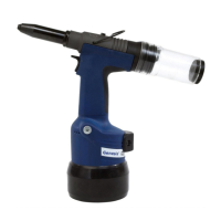
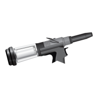
HANDLE ASSEMBLY (07271 & 07274 Models)
To remove handle assembly 56, remove cushion 57 to gain access to screws 36.
Remove six (07271 Model), or four (07274 Model) screws 36.
Remove handle assembly 56.
Remove the trigger valve by unscrewing adjuster 50 and lifting out button 49.
Withdraw valve plunger 43, spring 46, valve plunger washer 51 and plunger seal 47.
The design of the valve is such that a minimum of service is required during the tool life. Servicing should only be carried out if
absolutely necessary.
If so, unscrew retaining screw 44, withdraw spring 45, ‘O’ ring 48 and ball 42.
When assembling lubricate bores with Moly Lithium grease EP 3753.
When assembling replace retaining screw 44 using a low strength anaerobic adhesive (e.g. Permabond A121 or A137). The
adhesive should be spread under the head of retaining screw 44 for an approximate length of 3.2 mm (
1
/8") along the screw thread.
Always fit a new self adhesive cushion 57.
Complete assembly in reverse order of dismantling.
Every 500000 cycles the tool should be completely dismantled and components replaced where worn, damaged or when recommended.
All ‘O’ rings and seals should be renewed and lubricated with Moly Lithium grease EP 3753 before assembling.
The airline must be disconnected before any servicing or dismantling is attempted, unless specifically instructed otherwise.
It is recommended that any dismantling operation be carried out in clean conditions.
Item numbers in bold refer to the general assembly and parts list on page 25 and 26.
Prior to dismantling the tool, you will need to remove the nose equipment.
For total servicing of the tool itself, we advise you proceed with dismantling of sub-assemblies in the order shown below, starting with
either the handle assembly or the manifold assembly, depending on your model.
M A I N T E N A N C E
For all servicing we recommend the use of the service kit below (part number 07900-02700).
I M P O R T A N T
Safety Instructions appear on page 2 & 3.
The employer is responsible for ensuring that tool maintenance instructions are given to the appropriate personnel.
The operator should not be involved in maintenance or repair of the tool unless properly trained.
■
■
■
■
■
■
■
■
■
■
■
* refers to items included in the Avdel service kit. For complete list see above.
07900-00203 TORQUE WRENCH 1
07900-00204 BARREL NUT ADAPTOR ASSEMBLY 1
07900-00206 CYLINDER ASSEMBLY TOOL 1
07900-00238
7
/
16
" x
3
/
8
" SPANNER 1
07900-00181 LOCK RING KEY 1
07992-00020 80gm MOLYLITHIUM GREASE E.P.3753
1 TIN
07900-00009
3
/
32
" ALLEN KEY 1
07900-00013
1
/
8
" ALLEN KEY 1
07900-00157 CIRCLIP PLIERS 1
07900-00092
7
/
8
" x
3
/
4
" SPANNER 2
07900-00158 PIN PUNCH 1
07900-00201 0.05" ALLEN KEY 1
ITEM PART Nº DESCRIPTION Nº O
ITEM PART Nº DESCRIPTION Nº OFF
SERVICE KIT
NOTE: Spanner sizes are measured 'across flats' unless otherwise specified.
22
 Loading...