HC-2 CONTROLAIR
®
VALVE
Service Information
Description of Models
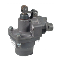
The HC-2 Type Controlair Valves are handle
operated 4-way, exhausted center, pressure
control valves.
The typical unit contains two directional control
3-way side valves and a pressure graduating
portion that is arranged to increase, decrease
or maintain air pressure to (2) separate delivery
lines. In neutral position both 3-way side valves
exhaust both delivery lines. A movement of 10
degrees either side of center position opens
the appropriate side valve and directs pressure
to the indicated outlet port. Continued move-
ment past 10 degrees up to full travel or 46
degrees either side of neutral continues to ac-
tuate the pressure-graduating portion to deliver
a graduated pressure according to the value of
the control spring.
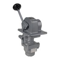
Models
There are four models with similar valve func-
tions, but different handle operating character-
istics.
HC-2-X Controlair Valve -Handle is spring
returned to neutral position from all positions in
the handle travel. Some special models exist.
See notes on Identity schedule on page 7.
HC-2-LX Controlair Valve - Handle is spring
returned to neutral position from all positions
except at the maximum pressure setting on
both sides of center. The handle is held in both
extreme positions by a mechanical detent.
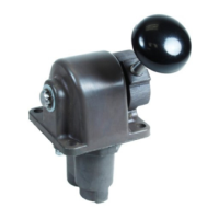
HC-2-FX Controlair Valve - Handle is
equipped with a friction brake that will hold the
handle in any position selected in the handle
travel.
HC-2-SX Controlair Valve - Handle holds in
only one maximum pressure position. The han-
dle is spring returned to neutral position from
all other positions in the handle travel. The
valve can be ordered to hold in either extreme
position.
Table of Contents Page
Description of Models 1
Warnings 2
Technical Data 2
Installation 2
Maintenance and Repair 2
Outline Dimensions 3
Descriptions of Operation 4
Maintenance and Repair 5
Graphical Symbol 6
Identity Schedule 7
Exploded View 8
Part List 9
Repair Kit List 10
Testing
Function 11
Pressure Range 11
Leakage 11
Flow Capacity 11
Response 11
Mechanical Detents 11
Test Setup 11
Test Diagram 12
SM-800.6505