Circuit Description
The 6600 module consists of two identical input circuits and two identical groups of four
output circuits. A jumper (H2) permits the two output channels to be both connected to
one input channel for use as a one input, eight output monaural amplifier or a two
channel, four output stereo amplifier.
Since both input amplifiers are the same, only the A channel will be described.
The differential input signal is applied to the inverting inputs of U3:A and U3:B. An
inverted version of the common mode signal (if any) is also applied to these inputs from
U6:A such as to cancel any common mode component at the outputs of U3:A and U3:B.
The outputs from U3:A and U3:B are then applied to the differential amplifier, U6:B.
Optimum common mode balance is achieved by adjusting RV3 at the output of U6:A.
The output from the differential amplifier passes via the gain control potentiometer, RV1,
to the programmable gain amplifier, U5:A. This amplifier provides fixed gains of 0dB,
+9dB, +18dB and +27dB. The desired gain is set by H1.
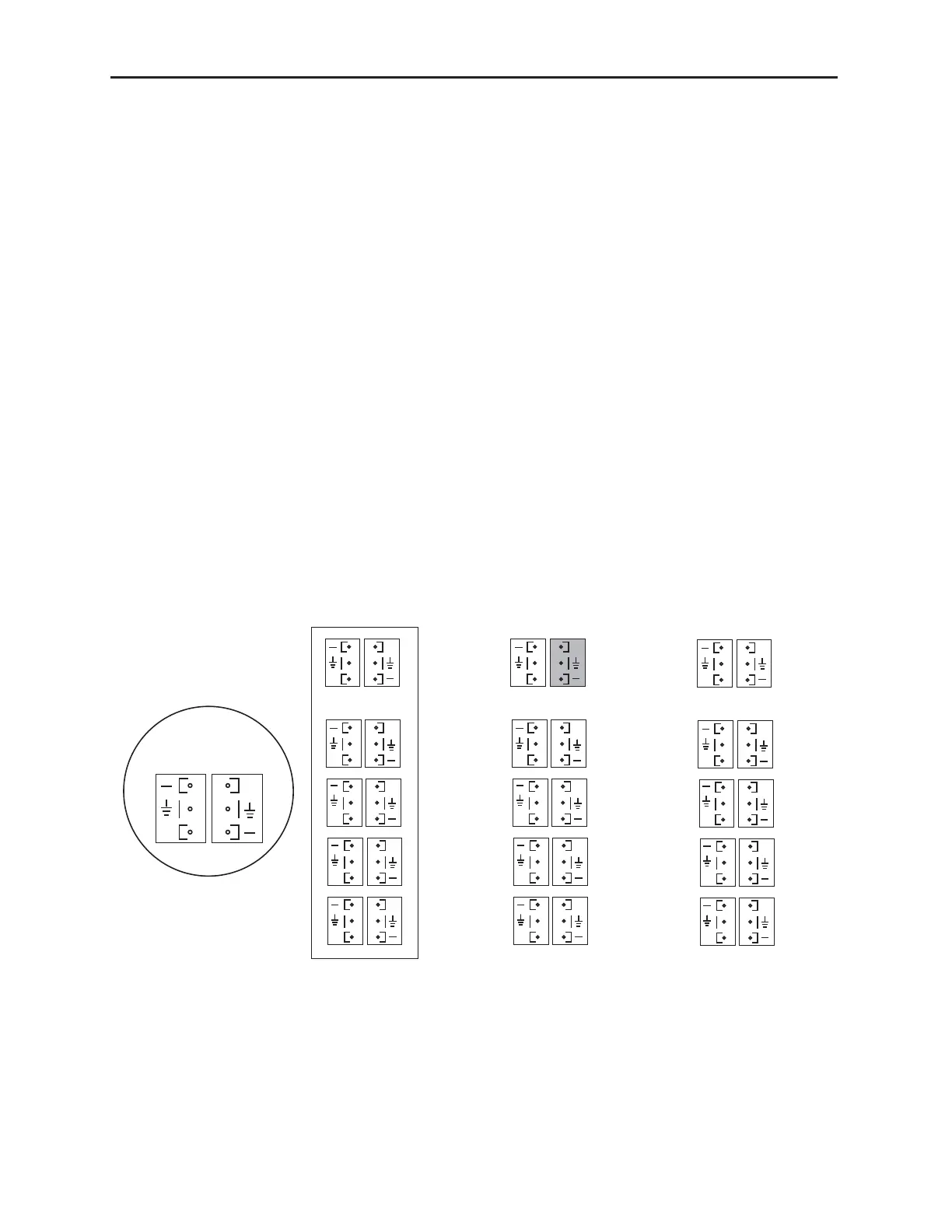
Cabling
Audio input and output cabling consists of 3-pin terminal blocks as shown in the illustra-
tion below. For MONO operation, connect audio to the CH A input only and use the eight
monaural outputs. For STEREO operation, connect audio to the CH A and CH B inputs
and use the four CH A and four CH B outputs as shown. Connectors grayed out are not
used for the application.
Model 6600 Analog Audio DAs and Frame
6600-6
 Loading...