The document provided is a service guide for Avid Ball Bearing Disc Brakes, covering both TYPE F and TYPE N models. This guide is intended for professional bike mechanics due to the safety-critical nature of brake components.
Function Description:
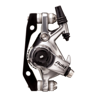
The Avid Ball Bearing Disc Brake is a bicycle braking system that utilizes ball bearings for its actuation mechanism, providing a mechanical disc braking solution. The system consists of a caliper body, a drive cam, a fixed cam, ball bearings, pressure feet (inboard and outboard), and various adjustment knobs and seals. When the brake lever is actuated, the cable pulls on the torque arm, which rotates the drive cam. The ball bearings, positioned in ramps between the drive cam and fixed cam, cause the drive cam to push the outboard pressure foot inward, clamping the rotor between the pads and applying braking force. The inboard pressure foot is adjusted manually to set the initial pad position.
Important Technical Specifications:
- Torque Specs:
- Lockring: 140-150 In. Lbs
- Torque Arm Fixing Nut: 55-60 In. Lbs
- Truss Bolts: 50-55 In. Lbs (These bolts are tamper-proof and should not be removed; their torque can only be checked with the proper tool.)
- Recommended Grease: Grease with a minimum temperature rating of 400 degrees Fahrenheit, such as Tri-Flow™ High Performance Synthetic Grease with Teflon® or Pro-Gold EPX Cycle Grease.
- Thread-lock: High-strength thread-lock like Loctite 272 is recommended for certain components, specifically the drive cam threads.
- Pad Spacer: A 2mm pad spacer is used during assembly to ensure proper clearance. If fabricating a spacer, use cardboard or similar material that won't damage the friction material.
- Caliper Body: One-piece body design incorporating two Truss Bolts for strength.
- Pad Spreader Clip (TYPE N only): Utilizes a pad spreader clip between the pads to keep them retracted, replacing the magnet system used in older designs. The new design has no external protrusions.
Usage Features:
- Outboard Adjuster Knob: Allows for adjustment of the outboard pad position. Turning it counter-clockwise retracts the pressure foot. Care must be taken not to turn it too far clockwise without a rotor, as this can dislodge the outboard pressure foot.
- Inboard Adjuster Knob: Allows for adjustment of the inboard pad position. Turning it clockwise moves the pad inward.
- Spring Tension Adjustment Screw (TYPE F only): A 2.5mm hex wrench is used to adjust spring tension on TYPE F calipers.
- Pad Replacement: The system is designed for easy pad replacement, with a pad retainer clip in the caliper body.
- Model Identification: TYPE F calipers have a red Avid logo badge, while TYPE N calipers have a red and white Avid logo decal on the back of the body.
Maintenance Features:
The service guide details a comprehensive overhaul process, including disassembly, cleaning, inspection, and reassembly.
-
Disassembly:
- Removal of cable anchor bolt and plate, cable housing, and inner wire.
- Removal of cable boots and, for TYPE F, the separate housing ferrule and spring tension adjustment screw.
- Step-by-step removal of the outboard knob, footscrew, torque arm, outer body seal, spring, hex-hole washer, spring adjuster plate (TYPE F), and lockring retainer.
- Use of specific tools like the Avid MDT-1 lockring tool, 3/8 drive ratchet, 11mm socket/wrench, 1.5mm and 5mm hex wrenches, flat-blade screwdriver, torque wrench, and small needle-nose pliers or Schrader-valve tool.
- Removal of the cam/outboard pressure foot assembly, pads, pad spacer, inboard adjuster knob, and inboard pressure foot.
- Careful removal of the inner body seal using an x-acto knife or sharp tool at the split.
- Disassembly of the cams, ensuring ball bearings are not lost, and unthreading the footscrew from the drive cam.
-
Cleaning & Inspection:
- Cleaning all metal parts in solvent and cable seals/boots in mild soap and water.
- Thorough inspection of the caliper body for damage, especially threaded surfaces and the pad retainer clip.
- Inspection of small parts: ball bearings and cam ramps for wear (ball tracks are normal), threads of the drive cam, footscrew, lockring, inner pressure foot, cable anchor bolt, and torque arm fixing nut for damage.
- Inspection of the spring for damage.
- For TYPE F calipers, verification of pressure foot magnets.
- Inspection of inner body seal, outer body seal, and cable seal boots for nicks, tears, or cracking.
-
Assembly:
- Installation of the inner body seal, ensuring the groove faces down and it's seated in its recess.
- Light greasing of the entire body bore, lockring threads, inner pressure foot threads, and inner knob detents.
- Installation of the inner pressure foot and inboard adjuster knob.
- Re-mounting the caliper onto the bike.
- Installation of pads and pad spacer, locking them into place with the inboard adjuster knob.
- Light greasing of cam parts: footscrew threads, stem-end of outer pressure foot, and ramps of drive cam and fixed cam.
- Installation of the footscrew into the drive cam and the outboard pressure foot.
- Assembly of the cams, ensuring ball bearings are properly seated in the ramps.
- Installation of the cam assembly into the caliper body, aligning the tab on the fixed cam with the groove in the caliper body, and pressing it in by the fixed cam.
- Installation and torquing of the lockring (140-150 In. Lbs).
- Installation of the lockring retainer, aligning the tab with the cut-out on the fixed cam.
- For TYPE F only: Installation of the spring adjuster plate and spring adjuster screw.
- Installation of the hex-hole washer.
- Application of thread-lock (Loctite 272) to the drive cam threads, avoiding the footscrew area.
- Installation of the spring, engaging the tab into the hole of the spring adjuster plate (TYPE F) or fixed cam (TYPE N).
- Installation of the outer body seal, engaging the spring tab into the hole in the boot.
- For TYPE N only: Installation of the spring adjuster.
- Careful orientation and installation of the flat washer, detent washer (rounded edge up), and torque arm fixing nut.
- Installation of the torque arm, ensuring proper orientation (below the bottom truss bolt for MTB calipers, below the front truss bolt for ROAD calipers on 2002 MTB calipers).
- Installation of the flat washer and detent washer (rounded edge up) over the drive cam shaft.
- Installation and torquing of the torque arm fixing nut (55-60 In. Lbs).
- Installation of the outer knob, aligning the rectangle tab of the footscrew with the hole in the knob.
- Installation of cable seals (TYPE F: upper and lower seals onto the cable ferrule and into the cable stop; TYPE N: upper and lower boots onto the integrated cable stop).
- Installation of the cable anchor bolt and plate, greasing the bolt lightly.
- Removal of the pad spacer.
- Final setup following Avid's BBDB Installation Guidelines.