- 4 -
IST0649V1/0
RECEIVER
A- B
C
GUASTOALLARME
S7
NC
C
NO
NC
NO
S8
OUT
+F
+
S6
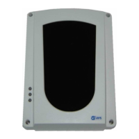
The terminal board is made of
two separate groups: the one
on the left concerns alarm
and fault-condition output
whilst the one on the right
concerns supplying input and
serial door.
ON/CN
MRALA
.yalerMRALAfoegnahcxE
.detcetedneebsahekomsretfasdnoces04tuobaevitcasitI
.ON/CroCN/Cegnahcxeehttesotredroni7SrepmujnotcA
ON/CN
TLUAF
-OITIDNOC
N
.yalerTLUAFfoegnahcxE
neddusadetcetedsahmaebehtretfaetunim1tuobaevitcas'tI
.levelmuminimehtrednulangisehtfoesaerced
.ON/CroCN/Cegnahcxeehttesot8SrepmujnotcA
C
F+TUO
fonoitcennoctceridehtswollatuptuosihT.yalermralaehtsasetavitcatI
ehtmralagniruD.tinulortnoceriflanoitnevnocfoenilenootmaebeht
.mho086siegrahcecnetsiser
+ )V8,72xam/V5,11.nim(V42roV21evitisopgniylppuS
- evitagengniylppuS
A
001RBeludomlanoitpootnoitcennocrofroodlaireS
B
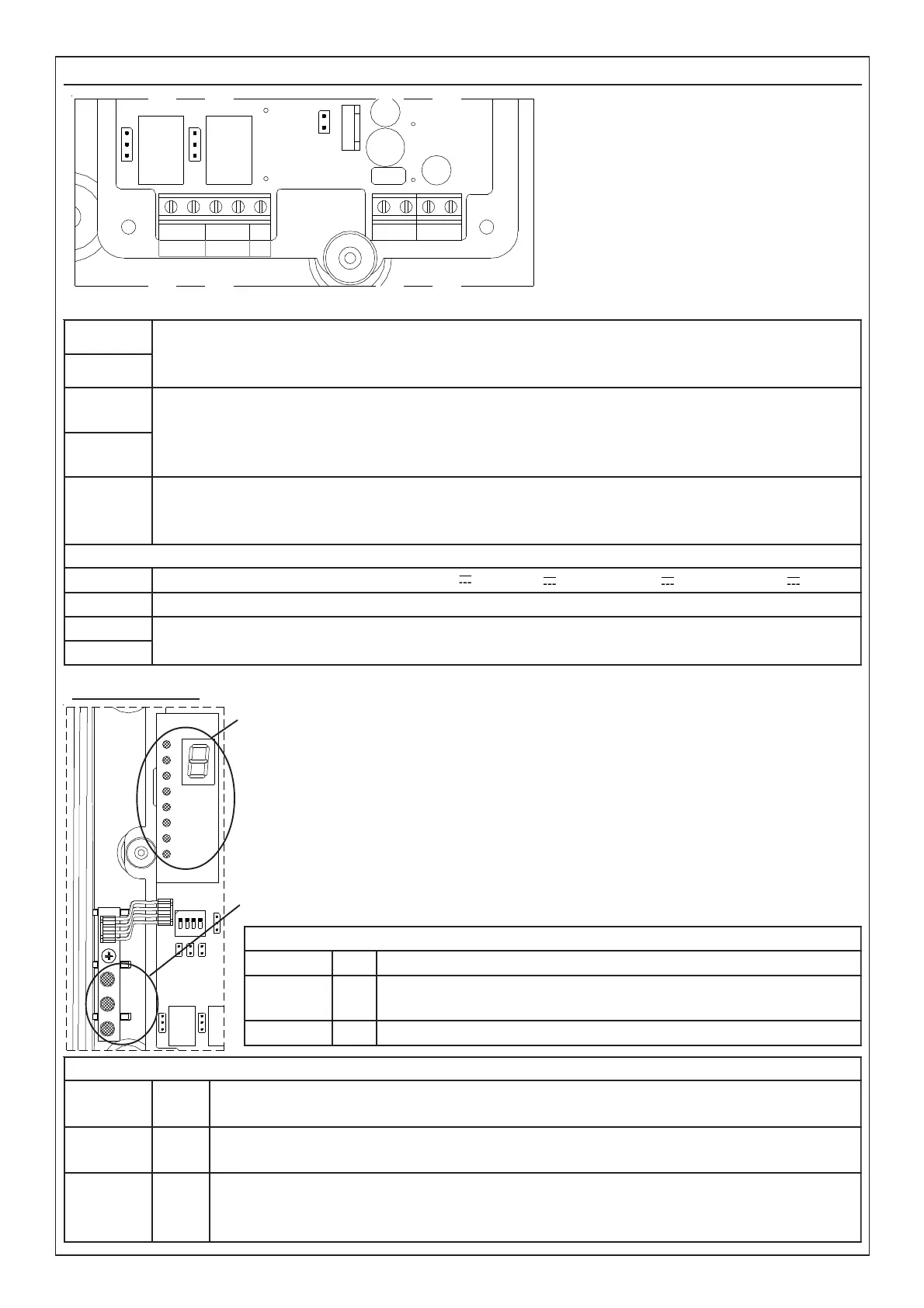
Signalling Led
Module to visualize the signal:
– during normal working, the display will visualize the unit values while
the Led bar will visualize the decimanl values of the signal received.
– during alarm condition the letter A is visualized.
– during fault condition the letter F is visualized.
- during calibration the display visualizes the unit values whilst the Leds
bar visualizes the decimal values of signal received.
Module for visualization of detector condition:
EDOMNOITARBILAC
DER
2DL
FFO
NEERG
3DL
detcetedtonsirettimsnarTehtfolangisehtfi:FFO
detcetedsilangisrevieceRehtfi:NO
WOLLEY
4DL
FFO
EDOMLAMRON
DER
2DL
FFO
NO
noitidnoclamroN
mralA
NEERG
3DL
gnihsalfwolS
gnihsalfkciuQ
)sdnoces2yreve(noitidnoclamroN
dlohserhtmralaehtgnideecxeekomshtiW
WOLLEY
4DL
FFO
gnihsalfkciuQ
NO
noitidnoclamroN
mrala-erpnoitidnoctluaf(muminimrednulevellangiS )
noitavitcayalertluaffoemitemasehttA
LD3
LD4
2
3
4
5
6
7
8
LD2
1
 Loading...