EasyManua.ls Logo

AVS Electronics BF100 A User Manual

AVS Electronics BF100 A
16 pages
To Next Page IconTo Next Page
Page #1 background imageLoading...
Page #1 background image
- 1 -
IST0649V1/0
IST0649V1/0
BF100 ABF100 A
BF100 ABF100 A
BF100 A
SmokSmok
SmokSmok
Smok
ee
ee
e
detectiondetection
detectiondetection
detection
beambeam
beambeam
beam
AA
AA
A
VS ELECTRVS ELECTR
VS ELECTRVS ELECTR
VS ELECTR
ONICSONICS
ONICSONICS
ONICS
CurCur
CurCur
Cur
tartar
tartar
tar
olo (Polo (P
olo (Polo (P
olo (P
adoado
adoado
ado
vv
vv
v
a) Itala) Ital
a) Itala) Ital
a) Ital
yy
yy
y
wwwwww
wwwwww
www
.a.a
.a.a
.a
vselectrvselectr
vselectrvselectr
vselectr
onicsonics
onicsonics
onics
.com.com
.com.com
.com
In conformity to EN54 norms
CERTIFIED
QUALITY SYSTEM
ISO9001
Question and Answer IconNeed help?

Do you have a question about the AVS Electronics BF100 A and is the answer not in the manual?

AVS Electronics BF100 A Specifications

General IconGeneral
BrandAVS Electronics
ModelBF100 A
CategoryMeasuring Instruments
LanguageEnglish

Summary

GENERAL FEATURES

Product Description and Functionality

Details the smoke detection beam, its transmitter/receiver components, and its primary function in detecting smoke.

CALIBRATION PROCEDURE

Alignment and Initial Setup

Covers rough alignment using the view-finder, checking jumpers, and setting dip switches.

Signal Adjustment and Sensitivity Setting

Details activating calibration mode, adjusting signal with RV1, and setting sensitivity levels.

NORMAL OPERATION MODES

LED Status Indicators Explained

Explains the meaning of green, red, and yellow LEDs during normal, alarm, and fault conditions.

BR100 REMOTE PANEL

Connection and Addressing Beams

Details how to connect and address individual beams to the BR100 remote panel.

CONTROL UNIT CONNECTIONS

Direct Connection (OUT +F)

Explains direct connection for alarm signaling to conventional fire control units.
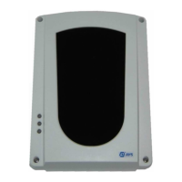