- 28 -
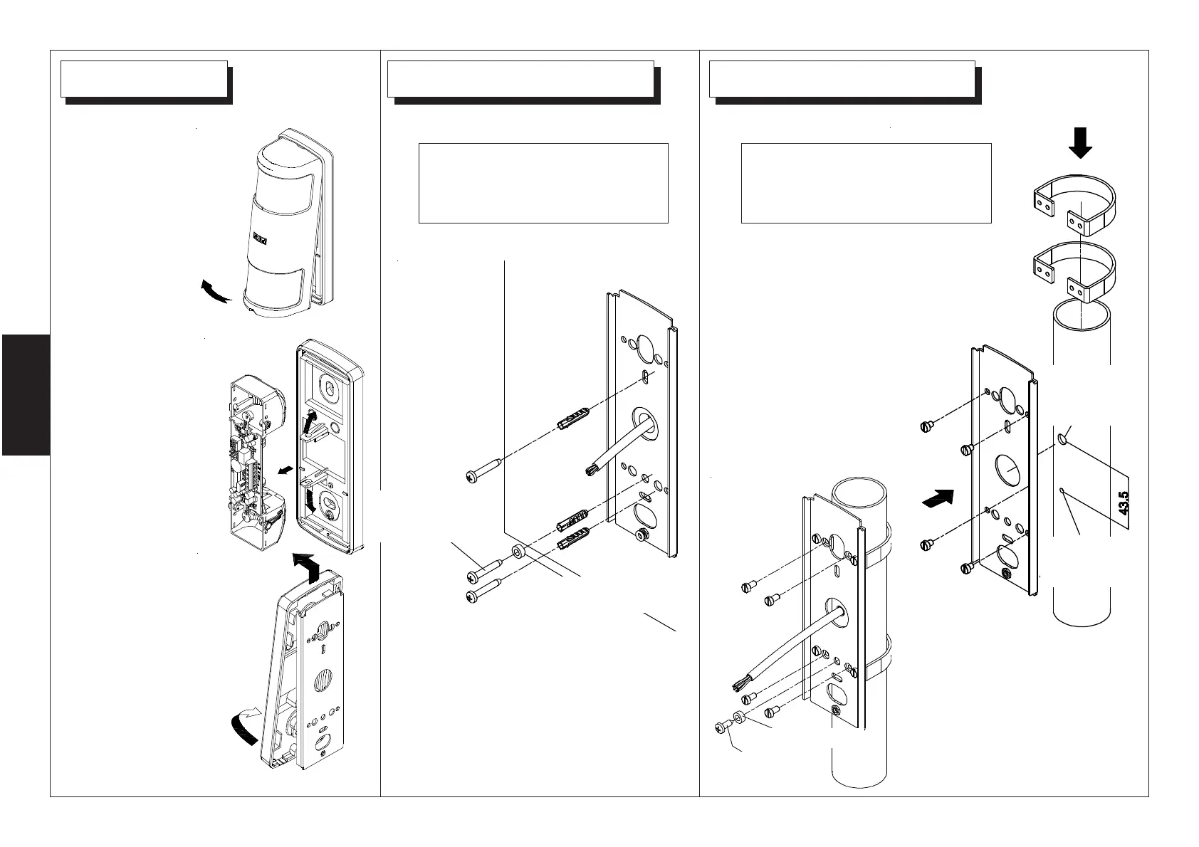
To install the removable
tamper kit, see instructions
on page n.5..
To install the removable
tamper kit, see instructions
on page n.5..
1
Remove the cover
2
Remove the
electronic board
slightly bending the
rear plastic
supports
3
Remove the
electronic board
slightly bending
the rear plastic
supports from the
back plate
To Wall Mount the back plate, use 2
dowels (Ø 5).
Tamper screw hole must
have a diameter of 3,25
mm.
CWith post mounting optional kit
(KIT SP) fix the post bracket to the
back plate using M4 x10 screws
(side figure)
then fix the back plate (using the
M4 x10 screws) to the post.
(see figure below)
ANTI-TAMPER
SCREW
SPACER
SPACER
ANTI-TAMPER
SCREW
HOLE
FOR
CABLE
HOLE FOR
ANTI-TAMPER
SCREW