- 29 -
WARNING
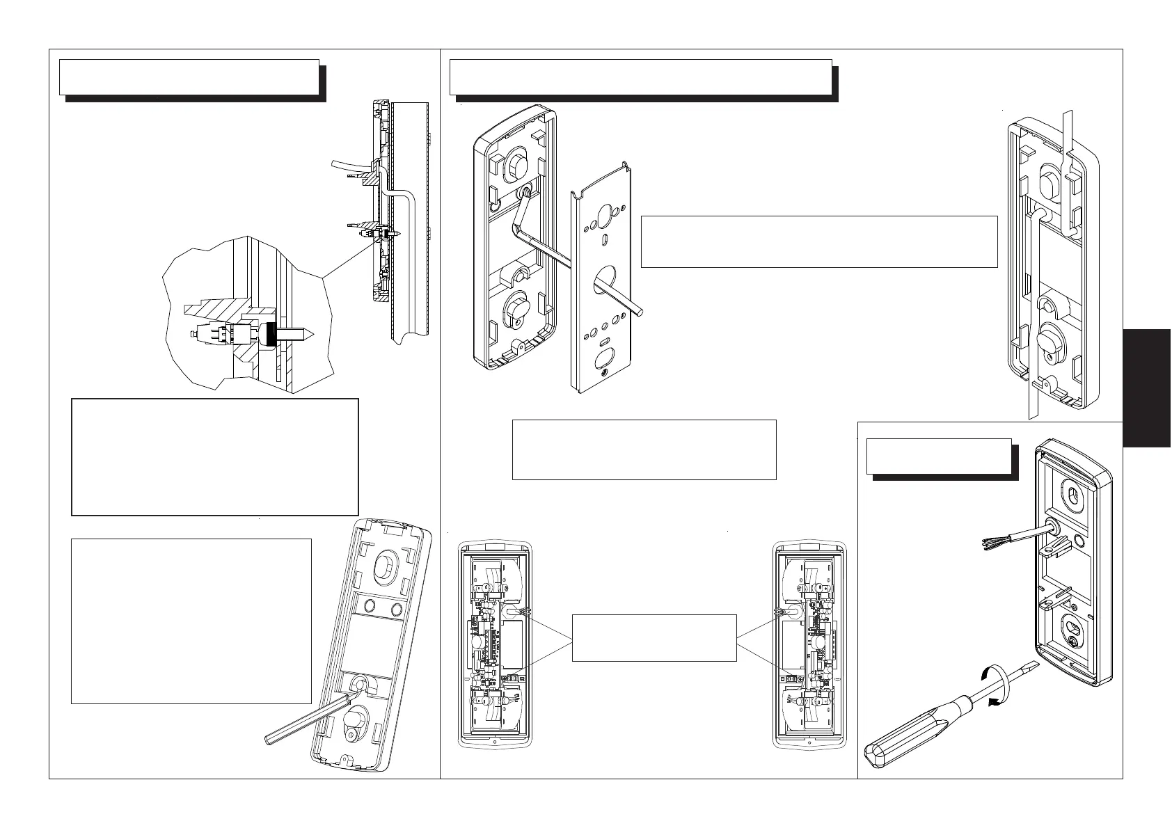
To use the wall tamper, remove
completely the protection cap
at the back of base.
Install the fair-lead on the base hole to lead
the wire.
Wiring hole SPIDER PA and SPIDER DUAL
If the electronic board is
mounted front-oriented, the
hole and the wire can be
placed indifferently in both
sides
If the electronic board is to be mounted side- oriented,
place the wire inlet hole and the wire iteself
at the opposite side, like
depicted in the drawings.
To mount the detector use, for the
removable tamper screw, the
spacer ring.
If the wiring inlet is from the back of
the detector, use the central hole
on the back plate. (left picture).
If the wire inlet is from a side of the
detector, use the side break
through holes. (right picture).
To fix the base to the
back plate, use the
screw with ring.
ATTENZIONE
Nei modelli SPIDER PA e SPIDER
DUAL, la mancata applicazione del
dispositivo anti-apertura/anti-strap-
po fa decadere la certificazione IMQ