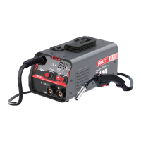
The AWT MIG-140 is an inverter welding machine capable of Flux-Cored MIG and STICK (MMA) welding. It is designed for both experienced welders and beginners, featuring a SYNERGIC SET function that simplifies operation.
Function Description
The MIG-140 performs two primary welding processes:
- Flux-Cored MIG Welding (Gasless): This process does not require a separate shielding gas, as the welding wire contains special additives (flux) that protect the weld as it cools. It is ideal for welding steel, mild steel, and stainless steel, particularly for medium to thicker materials, or when welding on painted or rusty steel. It is also suitable for outdoor applications where wind might blow away MIG shielding gas. While it produces a good weld, its appearance may not be as excellent as traditional MIG welding with gas. The machine offers both Synergic and Manual modes for Flux-Cored MIG.
- STICK Welding (MMA - Manual Metal Arc): This process uses coated electrodes to create the weld.
The SYNERGIC SET function for Flux-Cored MIG welding allows the user to weld like a professional without extensive prior experience. In Synergic mode, the wire feed speed and voltage are automatically adjusted based on the selected wire diameter and amperage, simplifying the setup process.
Important Technical Specifications
- Model: MIG-140
- Rated Input Voltage: AC 110V ±15% 50/60Hz
- Rated Input Power: 4.1 KVA
- Rated Input Current: 36.5 A
- MMA Welding Current Range: 20A ~ 115A
- MIG Welding Current Range: 20A ~ 120A
- No-Load Voltage: 60V
- Rated Duty Cycle: 25% at 120 Amps for 110 Volts. This means the machine can weld for 2.5 minutes within a 10-minute block, followed by 7.5 minutes of cooling. If the duty cycle is exceeded, the machine automatically shuts off for cooling.
- Enclosure Protection: IP21S (protected against solid objects over 12.5mm and vertically falling water drops).
- Wire Feed Speed Range: 2.5 - 11 m/min
- Power Factor: 0.73
- Insulation Class: F
- Cooling Type: Wind Cooling
- Dimensions: 370 x 195 x 260 mm
Usage Features
Controls and Operational Features (Front Panel):
- Current Display: Shows the welding current.
- Voltage Adjustment Knob: Adjusts the arc voltage or "heat" (low to high). Different materials and thicknesses require different settings. This is a scale, not actual voltage.
- Amp/Wire Feed Knob: In MMA mode, it adjusts welding amperage. In Flux-core mode, it adjusts output current, which in turn controls wire feeding speed. In synergic mode, wire feeding speed automatically changes with amperage adjustment.
- Welding Mode Selection Button ("CHOOSE"): Allows switching between .030" Flux-core Wire, .035" Flux-core Wire, and Stick Welding (MMA). Press and hold for 3 seconds to activate Synergic mode.
- Power Light: Illuminates when the power source is on and the torch switch is triggered.
- Over Heating Protection Indication (Protection Indicator Light): Turns on if the machine overheats or experiences over-current, indicating the inner temperature is above the permitted level. Welding can resume once the light turns off.
- MIG Gun Socket: Connection point for the MIG torch.
- Positive Output Terminal: For connecting the electrode holder (MMA) or earth clamp (MIG).
- Negative Output Terminal: For connecting the earth clamp (MMA) or electrode holder (MIG).
Rear Panel Features:
- Input Power Cable: Connects to the power supply.
- Power Switch: Turns the machine ON/OFF.
- Cooling Fan: Provides wind cooling.
- Rating Plate: Displays machine specifications.
Installation and Setup for MIG (Gasless):
- Ensure the power switch is OFF.
- Connect and tighten the weld power cable.
- Connect and tighten the earth clamp into the Positive socket (+). Loose connections can cause overheating.
- Install the correct knurled drive roller for gasless flux-cored wire, matching the wire diameter to the drive roller and contact tip.
- Place the wire spool onto the spool holder (note: spool retaining nut is top thread). Feed the wire through the inlet guide tube to the drive roller.
- Carefully feed the wire over the drive roller into the outlet guide tube, about 150mm in.
- Align the wire into the groove of the drive roller, close the top roller, and lock the pressure arm.
- Apply light pressure to the drive roller; excessive pressure can crush the cored wire.
- Remove the gas nozzle and contact tip from the torch neck.
- Switch the power source ON.
- Press and hold the MIG Torch switch to feed the wire through to the torch neck.
- Fit the correct sized contact tip, feed the wire through it, screw it into the tip holder, and tighten.
- Screw the nozzle to the torch head. Use pliers to cut the wire to about 10mm.
Wire Loading and Threading:
- Turn the power switch OFF.
- Ensure the drive roll and contact tip match the wire diameter and type.
- Push the spool onto the spindle so wire feeds from the bottom, towards the drive roll.
- Push the spool spacer onto the spindle, against the spool.
- Slide the spring onto the spool, then press and turn the spool lock clockwise.
- Release the spring-loaded thumb screw and rotate the idle roll arm away from the drive roll.
- Detach wire end from spool, maintaining tension.
- Cut bent wire portion and straighten the first 4" (100mm).
- Thread wire through incoming guide tube, over drive roll, and into gun liner.
- Close idle roll arm and turn thumbscrew until idle roller presses firmly on wire.
- Adjust pressure on the idle roll arm to prevent spool overrun but allow smooth feeding.
Wire Stick Out:
- Remove contact tip and nozzle.
- Turn machine ON.
- Straighten gun cable.
- Depress gun trigger to feed wire (point away from self/others). Release when wire appears at gun end.
- Turn machine OFF.
- Install nozzle and contact tip. Cut wire to 3/8" to 5/8" (10-15mm) stick-out.
- Turn machine ON, ready to weld.
MMA/Stick Welding:
- Ensure the power switch is OFF.
- Connect the primary power supply cable to the rated input power.
- Ensure tight connection to avoid oxidation.
- Check voltage with a multi-meter.
- Insert the cable plug with the electrode holder into the "+" socket on the front panel and tighten clockwise.
- Insert the cable plug with the earth clamp into the "-" socket on the front panel and tighten clockwise.
- Insert the electrode into the electrode holder.
- Connect the ground clamp to a clean, bare metal surface of the workpiece.
- Turn on the power switch at the back panel.
- The welder is ready to use.
Welding Getting Started (Work Piece Cleaning):
The joint to be welded must be clean, free of rust, greasy dirt, water, and paint.
Maintenance Features
Safety Precautions:
- ELECTRIC SHOCK CAN KILL: Only qualified personnel should perform installation and service. Disconnect input power and allow capacitors to discharge (min. 5 minutes) before working inside. Insulate yourself from work and ground, wear dry insulating gloves. Do not touch electrically hot parts.
- WARNING (General): Do not open the machine or introduce anything into its openings. Disconnect power before maintenance/service. Perform proper tests after repair.
- CAUTION: Power supply must be disconnected before maintenance/service. Always use gloves.
Input Filter Capacitor Discharge Procedure:
- Internal capacitors are charged to high voltage during power-on. This voltage is dangerous.
- Discharging is automatic when power is switched off.
- Allow the machine to sit for at least 5 minutes after switching off to ensure full discharge before servicing.
Routine Maintenance:
- Frequency varies with the working environment. Report any noticeable damage immediately.
- Check cables and connections integrity; replace if necessary.
- Clean the power source inside using low-pressure compressed air.
- Keep the machine clean. Use a soft dry cloth to clean the external case, especially airflow inlet/outlet louvers.
Troubleshooting Guide:
The manual provides a detailed troubleshooting guide with common problems (symptoms), possible causes, and recommended solutions for issues like:
- Wire feeds but no arc.
- Arc works but no wire feeding.
- No arc or wire feed (fan operates normally or not).
- Low output or non-penetrating weld.
- Feed motor operates but wire won't feed.
- Wire "bird-nesting" or jamming.
- Wire burns back to contact tip.
- Ground clamp, ground cable, or welding cable getting hot.
- Gun nozzle arcs to work surface.
This comprehensive guide helps users identify and resolve common operational issues, ensuring safe and effective use of the AWT MIG-140.