Do you have a question about the Axell Wireless MBF-40 Series and is the answer not in the manual?
Provides Axell Wireless physical address and contact numbers.
Email address for commercial questions.
Official website for more information.
Email address for technical support.
Phone number for technical support.
Details what the manual covers: description, setup, and maintenance.
Specifies that the manual is for experienced technicians and engineers.
States the document is confidential and for authorized use only.
Limits manufacturer liability for document errors and product use.
Outlines warranty conditions and limitations for product use.
Details FCC rules, warnings, and exposure limits for operation.
Outlines Industry Canada regulations for radio transmitters.
Explains the meaning of "Caution" labels for procedures.
Warns about electrical shock risks during installation and modification.
Advises on safe handling, power settings, and equipment temperature.
Discusses RF radiation hazards and antenna placement recommendations.
Emphasizes safety during operation and restricted access.
Details ESD precautions for handling sensitive components.
Warns about Class 1 laser radiation from optical receptacles.
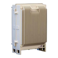
Describes the Multi-Band Fiber optic fed system and its applications.
Highlights high output power, convection cooling, and remote units.
Lists supported frequency bands and model variations.
Explains the Master/Slave configuration for five-band support.
Details MIMO enclosure and port support.
Specifies output power levels and low noise factor benefits.
Lists methods for remote setup and monitoring.
Explains how ALC maintains constant gain and prevents distortion.
Describes MIMO support and required OMU II configuration.
Details the Master/Slave units for five-band support over one fiber.
Illustrates connections for a quad-band Master and single-band Slave.
Discusses operating temperature and cooling mechanisms.
Explains remote commissioning and local access via IP address.
Lists physical interface types for security and connectivity.
Details how to secure the repeater with screws and optional lock.
Shows and describes ports for single service antennas.
Shows and describes ports for dual/MIMO service antennas.
Explains each port's function and connection type.
Lists internal connections needed for setup.
Illustrates internal components and connections for this model.
Shows internal components and their connections.
Shows internal view of a dual power supply unit.
Details MIMO model interfaces and optic converters.
Provides essential safety rules before repeater installation.
Lists factors for selecting an optimal installation site.
Recommends coaxial cable types, weather resistance, and connection practices.
Specifies guidelines for fiber optic cable installation and connector types.
Highlights installer accountability and interference avoidance.
Lists parameters needed for antenna selection and site considerations.
Suggests antenna types and gain specifications for indoor installations.
Details part numbers, frequency bands, and loss for splitters.
Lists part numbers, frequency bands, and coupling details for couplers.
French guide to indoor antenna conformity.
French guidelines for indoor antenna placement.
Details requirements for indoor antenna placement and tuning.
Covers considerations for outdoor antenna installation.
Warns about maximum input power limits.
Lists factors for choosing a repeater installation location.
Steps for unpacking the MBF-40 repeater and verifying contents.
Lists the items included with the MBF-40 repeater.
Describes wall and rack mounting options using brackets.
Illustrates how to attach mounting brackets to the MBF unit.
Specifies fixing to solid walls and avoiding hollow walls.
Suggests M6 rawlbolts and checking alignment.
Provides dimensions for marking drill points on the wall.
Details how to insert and tighten fixings for secure mounting.
Advises on lifting the heavy repeater and securing it tightly.
Notes compatibility and personnel requirements for fan hood installation.
Shows the MBF-40 with fan hood assembly.
Provides detailed measurements for the MBF-40 with fan hood.
Lists components included in the fan hood kit.
Recommends using only designed fan hoods and following instructions.
Details steps for assembling mounting brackets to the repeater.
Instructions for positioning and tightening the rear fan hood.
Shows assembled rear fan hood and brackets.
Steps for preparing the wall and mounting the repeater.
Instructions for attaching the front fan hood and tightening bolts.
Details how to connect power to the fan hood assemblies.
Notes differences for 5-band Master/Slave units.
Explains the 5-band system setup with Master and Slave units.
Lists cables needed for Master/Slave unit connection.
Advises on mounting distance and procedure for units.
Illustrates connections between Master and Slave without external alarms.
Details grounding, EMV protection, and cable connections.
Specifies routing of optic fiber and Ethernet cables internally.
Details port locations and connection types for external alarms.
Shows wiring for external alarms via RS-485 terminal blocks.
Emphasizes reliable grounding and cable dimensioning.
Details how to connect the repeater box bolt to ground.
Warns that insufficient EMV protection invalidates warranties.
Details protection against lightning surges for cables and equipment.
Illustrates EMV protection for a repeater system.
Explains using series protection devices and types.
Notes the need for a protective device on the power supply cord.
Warns about maximum input power for fiber optic connections.
Advises cleaning fiber connectors before connection.
Repeats laser safety warning for optical receptacles.
Specifies connector types and routing for fiber optic cables.
Details connecting fiber to the optic converter inside the repeater.
Explains routing fibers through a rubber seal for protection.
Instructions for adjusting fiber length and inserting the seal.
Completes the fiber optic connection procedure.
Describes the external alarm interface and connector plinth.
Shows the pin layout for external alarms and relay connections.
Details how to connect and configure external alarms.
Explains how to connect and configure relay outputs.
Reminds to connect antennas before powering on.
Specifies the need for an accessible circuit breaker.
Illustrates internal power components like battery pack and switches.
Lists specifications for the circuit breaker.
Details 115 VAC and -48 VDC power source options.
Explains the on/standby switch functionality.
Specifies cable requirements for 115 VAC connection.
Details SELV compliance and output power for -48VDC.
Provides cable area recommendations based on distance for 48VDC.
Explains the role of the backup battery for alarms.
Details how to switch the battery on/off and its connection.
Lists the sequence for switching on main, secondary, and battery power.
Clarifies the "on" and "stand by" positions of power switches.
Guides on checking module LEDs for correct operation.
Instructions for closing the unit and tightening screws.
Steps for establishing a local connection using USB and a web browser.
Instructions to open browser, type address, and login.
Provides default username and password for login.
Explains how to access MBF-40 through OMU II.
Describes the layout of the MBF-40 Web GUI, including tabs.
Shows the initial Home screen displayed upon login.
Explains the purpose of each main tab (Home, Nodes, Logs, Config, Logout).
Divides the Home screen into Controller, Alarms, Repeater Status, and Subsystems.
How to access the configuration screen via the Config menu.
Lists configuration options and their corresponding sections.
Shows the Home screen for a 5-band unit.
Shows serial numbers, versions, and site name.
Outlines steps for commissioning via OMU II.
How to perform OLA using the OMU II interface.
Lists OLA options, status, and results for each link.
Details steps to select nodes and perform adjustment.
Explains manual RF balancing via OMU II.
Outlines steps for balancing UL and DL outputs.
Steps to verify amplifier and set attenuation for downlink.
Steps to set uplink attenuation based on downlink settings.
States that automatic balancing is for future release.
How to access the automatic RF adjustment pane in OMU II.
Details steps for selecting bands and adjusting levels.
Explains automatic connection and configuration by AEM.
Advises on monitoring unit status and troubleshooting faulty nodes.
Differentiates between direct and indirect GUI sessions.
How to assign a recognizable name and view system info.
Steps to set the correct date and time for event timestamping.
How to configure alarm triggers and assign recognizable names.
Manual and DHCP methods for configuring the IP address.
How to configure ETH:TCP for remote communication.
Configuring trap destination addresses and port.
How to activate and configure the SNMP agent.
Steps to enable the SNMP Agent and set community parameters.
Lists default accounts for administration levels.
Describes different access levels (Read-Only, Read-Write, Web).
How to change the password for the current user session.
Steps to reboot the control module via the Config tab.
How to access the CLI pane for advanced commands.
Explains how to access and use the Attribute Reference for CLI commands.
Lists tools for monitoring and fault diagnosis (Web GUI, Logs, LEDs).
General warnings and advice for operation and maintenance.
How to access the MBF-40 Home window via OMU II.
Details the information presented in the advanced view.
Explains indicators like Temperature, Tag, Door Status, and Data Quality.
Describes band, amplifier, and power level indicators.
Explains module, comms, temperature, and optical status indicators.
Details status indicators for power supplies and reference generator.
Displays recent alarms and user actions chronologically.
Explains how to view log details and interpret status icons.
Introduces LEDs for internal modules like Controller, F/O, and Power.
Explains Blue (Login) and Red (Status) LEDs on the control module.
Describes LEDs for Power, Error, UL Data, DL Data, Rx Opto, Tx Opto.
Details LEDs for Input Power, +6V, +15V, and +28V.
Illustrates LED patterns for fault conditions.
Lists frequency ranges, bandwidths, and output power for US.
Details noise figure, ripple, propagation delay, and impedance.
Specs for wavelength, loss, and F/O connector.
Modulation accuracy metrics for different standards.
Specs for power usage, dimensions, weight, enclosure, and EMC.
Lists radio and safety compliances (FCC, UL).
Lists frequency ranges, bandwidths, and output power for Canada.
Details noise figure, ripple, propagation delay, and impedance.
Specs for wavelength, loss, and F/O connector.
Modulation accuracy metrics for different standards.
Specs for power usage, dimensions, weight, enclosure, and EMC.
Lists radio and safety compliances (IC).
Lists recommended tools for fiber optic cleaning.
Explains the dry cleaning process for optical connectors.
Continues dry cleaning steps including inspection and wet cleaning.
Details the wet cleaning technique using isopropyl alcohol.
Step-by-step guide for wet cleaning and subsequent dry cleaning.
| VSWR | < 1.5:1 |
|---|---|
| Power Supply | 110-240 VAC, 50/60 Hz |
| Operating Temperature | -20°C to +55°C |
| Weight | 12 kg |
| MTBF | > 100, 000 hours |
| Output Power | 40 dBm (Composite) |
| Noise Figure | 5 dB |