Do you have a question about the AXIOMA METERING UAB QALCOSONIC E4 and is the answer not in the manual?
Information on disposal of electrical and electronic equipment according to EU directive.
Key safety measures, risks, and prohibitions for operating the meter safely.
Accuracy class and available energy measurement units for the meter.
Details on flow rate ranges, sensor lengths, and pressure losses.
Specifications for pulse inputs, output types, pulse values, and frequency.
Information on the meter's display, data accumulation, and storage capacity.
Details on integrated and optional communication interfaces for data transfer.
Information on power options, overall dimensions, and weight of the meter.
Specifies operating temperature, humidity, and environment classes.
Explains the ultrasonic flow measurement and heat energy calculation formulas.
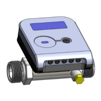
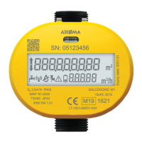
Information indicated on the electronic unit and flow sensor housing.
Outlines steps for sealing calculator, flow sensor, and temperature sensors.
Prerequisites and general rules before installing the heat meter.
Steps to check and modify meter settings before installation.
Guidance on connecting electrical components and interfaces.
Instructions for mounting the electronic unit (calculator) in various locations.
Recommendations for installing flow sensors horizontally, vertically, or sloped.
How to install temperature sensors perpendicularly or at an angle to the pipe.
How to use the control button and interpret data displayed on the LCD.
Navigating menus to view integral and instantaneous measured parameters.
How to access and interpret readings when the meter is in test mode.
Explanation of error codes and their meanings for troubleshooting.
Information on how the meter's metrological control is performed according to standards.
Recommendations for safe transport and storage of the meters.
Visual diagrams showing various meter connection configurations and labels.
Table detailing cable destinations and wire colors for extra cables.
Drawings showing overall dimensions of the calculator and flow sensors.
Diagrams detailing dimensions of temperature sensors and mounting pockets.
Visuals illustrating sealing methods for calculator and flow sensors.
Diagrams for temperature sensor installation and sealing methods.
Details of the warranty period and compliance requirements for the meter.
| Category | Ultrasonic water meter |
|---|---|
| Measurement Principle | Ultrasonic Transit Time |
| Battery Life | Up to 16 years |
| Protection Class | IP68 |
| Communication | M-Bus, Wireless M-Bus, RS-485 |
| Outputs | Pulse output |
| Power Supply | 3.6V Lithium battery |
| Storage Temperature | -25°C to 70°C |
| Nominal Diameter | DN15 |
| Pipe Diameter Range | DN15...DN40 |