Do you have a question about the AXIOMA METERING UAB QALCOSONIC E2 and is the answer not in the manual?
Danger from ~230 V electrical current during installation and maintenance.
Requirement for qualified technical personnel with certificates.
Selection of twelve possible measurement schemes based on application type.
Accuracy class and error calculation formulas for energy measurement.
Details on ultrasonic flow sensors and their specifications.
Sensor types, connection methods, ranges, and error considerations.
Modules and interfaces for data transfer and communication.
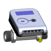
Various methods for calculator installation.
Installation diagrams, sensor wiring, and cable requirements.
Functionality of the calculator's control buttons.
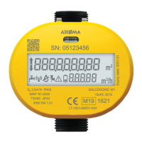
How the LCD displays information and its elements.
Details on significant faults and their codes.
Energy calculation formulas for U1, U2, U1F, U2F schemes.
Energy calculation formulas for U1A3, U2A3 schemes.
Diagram for temperature and flow sensors with 4-wire connection.
Diagrams for connecting to mains power and regulating valve.
Detailed dimensions for G3/4" flow sensors.
Dimensions for DN100-DN400 steel housing sensors.
Equipment compliance statement and warranty period.
| Brand | AXIOMA METERING UAB |
|---|---|
| Model | QALCOSONIC E2 |
| Category | Measuring Instruments |
| Language | English |