EasyManua.ls Logo

AXIOMTEK FAB111-7B1P4 - User Manual

AXIOMTEK FAB111-7B1P4
2 pages
Print Icon
To Next Page IconTo Next Page
Loading...
FAB111-7B1P4 Quick Installation Guide
©Copyright 2010 AXIOMTEK Co., Ltd.
Version A1 Apr 2010
Printed in Taiwan
9419B111010E
4
Board Dimensions
FAB111-7B1P4 Quick Installation Guide
©Copyright 2010 AXIOMTEK Co., Ltd.
Version A1 Apr 2010
Printed in Taiwan
9419B111010E
1
I. Checklist
9 FAB111-7B1P4 7-Slot ATX-Supported
PICMG 1.3 Bus Backplane x 1
9 Quick Installation Guide x 1
Note1: Please contact your local vendors if any damaged or missing items.
DO NOT apply power to the board if any damaged components.
II. Jumper List
Jumper Description
JP1
Open : ATX by CPU Card
Short : ATX Power Always On
JP2
(Reserved)
Auto : Power Button
Open : Disable
Short : Enable
III. Connectors
Connector Description
CN1 ATX Power Connector
CN2 12V 8Pin(+12V Auxiliary Power Connector)
CN3 8-Pin Power Connector for thermal board
CN4 SM Bus Connector
CN5,CN6,CN7 (Reserved) COM Ports and DIO Connector (Optional)
CN8,CN9,CN10,CN11(Reserved)
Thermal sensor Connector For FAN1;FAN2
&FAN3;FAN4(Optional)
USB1,USB2 USB 0,1,2,3
PWRBT1 ATX Power button connector
HWRST1 Hardware Reset Connector
FAN1,FAN2,FAN3,FAN4 FAN Connector
SHB1 – SHB4 PICMG 1.3 Full-SIZE SBC Slot
PCI1-PCI4 PCI Slots 32-bit/33MHz
PCIE1 X16 PCIe Slot
PCIEB1 X4 PCIe Slot (Note 2)
VR1,VR2,VR3,VR4 (Reserved)
Temperature Selection For FAN
Control(Optional)
Question and Answer IconNeed help?

Do you have a question about the AXIOMTEK FAB111-7B1P4 and is the answer not in the manual?

Overview

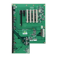
The FAB111-7B1P4 is a 7-slot ATX-supported PICMG 1.3 bus backplane, designed for industrial applications requiring robust and reliable performance. It serves as a central hub for connecting various components, including a CPU card, PCI/PCIe expansion cards, and peripheral devices, facilitating communication and power distribution within the system. The device comes with a Quick Installation Guide to assist with setup.

Function Description

The FAB111-7B1P4 backplane provides the necessary infrastructure for a modular industrial PC system. It integrates power distribution, data communication pathways, and various connectors for essential components. The PICMG 1.3 standard ensures compatibility with a wide range of single board computers (SBCs), allowing for flexible system configurations. Its primary function is to enable the interconnection and operation of a CPU card with multiple expansion cards, providing the foundation for specialized industrial applications.

Important Technical Specifications

  • Form Factor: 7-Slot ATX-Supported PICMG 1.3 Bus Backplane. This standard ensures compatibility with industrial-grade SBCs and expansion cards, offering high reliability and long-term availability.
  • Power Connectors:
    • CN1 (24-Pin ATX Power Connector): Supports standard ATX power supplies, providing various voltage rails (3.3V, 5V, 12V, -12V, -5V, 5VSB) for the backplane and connected components. Key signals include PSON (Power Supply ON) and PWOK (Power OK).
    • CN2 (8-Pin +12V Auxiliary Power Connector): Provides additional +12V power, crucial for high-power components or systems requiring stable 12V supply.
    • CN3 (Power Output Connector): Offers additional power outputs, including GND, -5V, 5V, -12V, 5VSB, 3.3V, and 12V, for specific peripheral needs.
  • Expansion Slots:
    • SHB1-SHB4: PICMG 1.3 Full-SIZE SBC Slots. These slots are designed for single board computers that adhere to the PICMG 1.3 specification, enabling high-performance CPU integration.
    • PCI1-PCI4: PCI Slots 32-bit/33MHz. Four standard PCI slots for legacy or specialized PCI expansion cards.
    • PCIE1: X16 PCIe Slot. A high-bandwidth PCIe slot for graphics cards or other high-performance PCIe devices.
    • PCIEB1: X4 PCIe Slot (Note 2). This slot is configured for a x4 PCIe link, capable of supporting x1 and x4 PCIe cards. It's important to verify compatibility with the SBC card vendor if a x4 PCIe card cannot be supported.
  • I/O Connectors:
    • CN4 (SM Bus Connector): Provides SM CLK and SM_DAT signals for System Management Bus communication, allowing for system monitoring and control.
    • USB1, USB2 (USB Connectors): Offers USB 0, 1, 2, 3 ports, including USB Power, USB P0-/P0+, USB P1-/P1+, and USB GND, for connecting various USB peripherals.
    • CN5, CN6, CN7 (Reserved): COM Ports and DIO Connector (Optional). These connectors are reserved for serial communication and digital input/output, depending on the specific configuration.
  • Fan Connectors:
    • FAN1, FAN2, FAN3, FAN4: Dedicated FAN Connectors (GND, +12V, N.C or Rotation Detection). These allow for connecting and controlling cooling fans, with optional rotation detection for monitoring fan status.
    • CN8, CN9, CN10, CN11 (Reserved): Thermal sensor Connector For FAN1, FAN2 & FAN3, FAN4 (Optional). These are reserved for connecting thermal sensors to enable temperature-based fan control.
  • Control Connectors:
    • PWRBT1 (ATX Power button connector): Connects to the system's power button for initiating system power on/off.
    • HWRST1 (Hardware Reset Connector): Connects to the system's reset button for performing a hardware reset.
  • Jumper Settings:
    • JP1 (Power Mode Selection):
      • Open: ATX by CPU Card (Power controlled by the CPU card).
      • Short: ATX Power Always On (System powers on automatically when power is supplied).
    • JP2 (Power Button Function):
      • Auto: Power Button (Standard power button functionality).
      • Open: Disable (Power button is disabled).
      • Short: Enable (Power button is enabled).
    • VR1, VR2, VR3, VR4 (Reserved): Temperature Selection For FAN Control (Optional). These jumpers are reserved for configuring temperature thresholds for fan control.

Usage Features

  • Modular Design: The PICMG 1.3 standard allows for easy integration and replacement of SBCs and expansion cards, simplifying maintenance and upgrades.
  • Flexible Power Control: Jumper settings for JP1 allow users to choose between CPU-controlled power or always-on power, catering to different application requirements (e.g., unattended operation).
  • Configurable Power Button: JP2 provides options to enable or disable the power button, preventing accidental shutdowns in critical applications.
  • Comprehensive Connectivity: A wide array of connectors for power, data, and peripherals ensures compatibility with various industrial components and external devices.
  • Thermal Management: Dedicated fan connectors and optional thermal sensor inputs allow for effective cooling solutions and temperature monitoring, crucial for stable operation in demanding environments.
  • Robust Construction: Designed for industrial use, the backplane is built to withstand harsh operating conditions, ensuring long-term reliability.
  • Easy Installation: The Quick Installation Guide provides clear instructions for setting up the backplane and connecting components.

Maintenance Features

  • Clear Labeling: All connectors and jumpers are clearly labeled on the board, simplifying identification during installation and troubleshooting.
  • Jumper-Based Configuration: Jumper settings provide a straightforward method for configuring power modes and power button functionality without requiring software changes.
  • Modular Component Replacement: The PICMG 1.3 architecture facilitates the easy replacement of individual components (SBCs, expansion cards) without needing to replace the entire system, reducing downtime and maintenance costs.
  • Damage Prevention Note: The manual explicitly warns against applying power to the board if any components are damaged or missing, emphasizing a critical step for preventing further damage during initial setup or troubleshooting.
  • Vendor Contact for Missing/Damaged Items: Users are advised to contact local vendors for any damaged or missing items, ensuring proper support and replacement parts.
  • Documentation: The Quick Installation Guide serves as a valuable resource for understanding the board's layout, connector pinouts, and jumper settings, aiding in troubleshooting and maintenance.
  • Version Control: The document includes version information (Version A1 Apr 2010) and a part number (9419B111010E), which is useful for tracking revisions and ensuring compatibility with other system components.

AXIOMTEK FAB111-7B1P4 Specifications

General IconGeneral
BrandAXIOMTEK
ModelFAB111-7B1P4
CategoryComputer Hardware
LanguageEnglish

Related product manuals