AXISP3245NetworkCameraSeries
Specifications
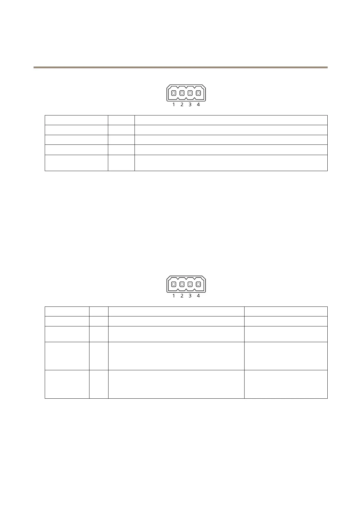
FunctionPinNotes
GND
1
Ground
Ringpower
2
12Vforexternalsource
Microphone/Linein
3
Microphone(analogordigital)orlinein(mono).5Vmicrophonebiasisavailable.
Lineout
4
Linelevelaudiooutput(mono).Canbeconnectedtoapublicaddress(PA)systemoran
activespeakerwithabuilt-inamplier.
I/Oconnector
UsetheI/Oconnectorwithexternaldevicesincombinationwith,forexample,motiondetection,eventtriggering,andalarm
notications.Inadditiontothe0VDCreferencepointandpower(DCoutput),theI/Oconnectorprovidestheinterfaceto:
Digitalinput-Forconnectingdevicesthatcantogglebetweenanopenandclosedcircuit,forexamplePIRsensors,door/window
contacts,andglassbreakdetectors.
Supervisedinput-Enablespossibilitytodetecttamperingonadigitalinput.
Digitaloutput-ForconnectingexternaldevicessuchasrelaysandLEDs.ConnecteddevicescanbeactivatedbytheVAPIX®
ApplicationProgrammingInterfaceorfromtheproduct’swebpage.
4-pinterminalblock
FunctionPinNotes
Specications
DCground
1
0VDC
DCoutput
2
Canbeusedtopowerauxiliaryequipment.
Note:Thispincanonlybeusedaspowerout.
12VDC
Maxload=25mA
DigitalInputor
SupervisedInput
3
Connecttopin1toactivate,orleaveoating(unconnected)
todeactivate.Tousesupervisedinput,installend-of-line
resistors.Seeconnectiondiagramforinformationabouthow
toconnecttheresistors.
0tomax30VDC
DigitalOutput
4
Internallyconnectedtopin1(DCground)whenactive,
andoating(unconnected)wheninactive.Ifusedwithan
inductiveload,e.g.,arelay,connectadiodeinparallelwith
theload,toprotectagainstvoltagetransients.
0tomax30VDC,opendrain,
100mA
Example
29