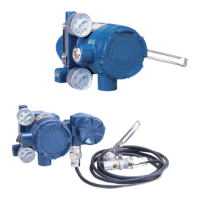
Appendix A: Specifications
A-17
Dimensions (Model AVP300/301/302)
[For single-acting actuator without KZ03 regulator]
unit: mm
*1. In terms of mechanical operation, do not exceed ±30°
Terminal Connection Diagram
(Terminal screw size: M4)
Mounting Plate Reference Diagram
16
7
9
70
32 64
90 min
Electrical connection*
2
Air piping connection*
3
G1/2 Rc1/4
1/2NPT 1/4NPT
M20×1.5 1/4NPT
With 40mm extension lever
187
*3
(Output air
pressure
connection)
*3
(Output air
pressure
connection)
82.5
18
124
15.6
13.1
With 40mm extension lever
74 180
6
Connector pin
52 110 40
220
Attach such that, when
the lever is horizonal,
the connector pin is
within this range.
Lever deflection*
1
±4° to ±20°
70 71
12
76.5
12
70
41.5
*2
14
82
43.5
34 9.5
(43.5)
M8 or
5/16-18UNC
Screw depth:
13.5
*2
Extension
lever
Actuator
model
Code
No
PSA1, 2 YS
HA1 YA
HA2, 3 YT
HK1 YK
Ye s
PSA3, 4
VA1–3
YQ
PSA6 YL
PSA7 Y8
HA4 YN
VA4–6 YL
VR1 YV
VR2, 3 YR
VR3H Y6
RSA1 YF
RSA2 YU
GOM83S,
84S, 103S
YG
GOM124S YM

 Loading...