2-25
Chapter 2: Installation
■ Flameproof cable gland installation procedure for AVP300
The procedure for mounting the flameproof cable gland is shown below.
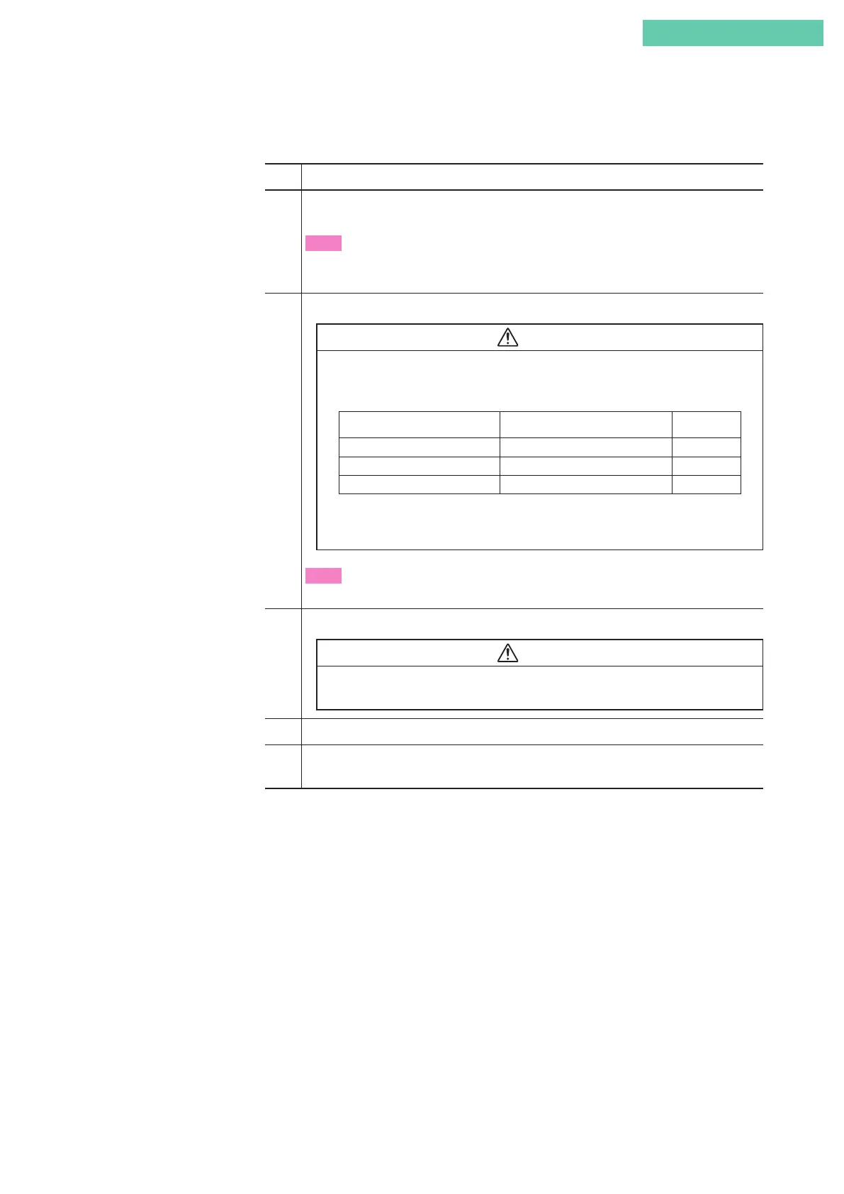
Step Procedure
1
Firmly tighten the entry body on the connection port and the universal elbow to hold it
in place.
Note
• Apply adequate waterproofing to these parts. We recommend the use of silicone resin
based non-hardening seal materials.
2
Refer to the illustrations and insert the cable carefully.
Warning
• If the diameters of the cable and the packing do not match each other, the propa-
gation of flame cannot be prevented. Refer to the table below and select a packing
adaptor whose internal diameter matches the outer diameter of the cable.
Cable Outer Diameter (mm) Packing Inner Diameter (mm) Notes
7.0 to 8.0 8 Provided
8.0 to 10.0 10 Built in
10.0 to 12.0 12 Provided
• The cable outer diameter is 8mm max., fix the cable gland with the
clamps.
Note
• Pay attention to the surface of the device. Tools may cause damage the surface.
3 Fit the coupling onto the clamp ring and tighten it down to hold it in place.
Warning
• To prevent injuries due to a spark travel, be sure to tighten down the packing ad-
equately.
4 Pass the cable through the body and insert it into the terminal box.
5 Screw the cover onto the body and tighten it down securely to hold it in place. Then,
tighten the union nut’s recess screw.