E4
WIRING
Wiring precautions
•
All wiring must comply with applicable codes and ordinances.
•
Do not run wires outside. The equipment could be damaged in
the event of lightning.
•
When connecting wires to the power terminals, use crimp ter-
minals with insulating sleeves.
•
Use M3 crimp terminal lugs for wiring to the power terminals
and the RS-485 CH2 terminals.
•
Be careful not to allow any crimp-type terminal lugs to touch
adjacent terminals.
•
The signal wires and power wires of the module should be at
least 60cm away from other power wires or power sources.
Also, do not pass these wires through the same conduit or wir-
ing duct.
•
Before connecting the NX-SVG to other devices in parallel,
check their connection conditions carefully.
•
To ensure stable operation, the NX-SVG is designed not to op-
erate for 30 seconds after the power is turned ON.
•
After wiring, check that there are no mistakes before turning
the power ON.
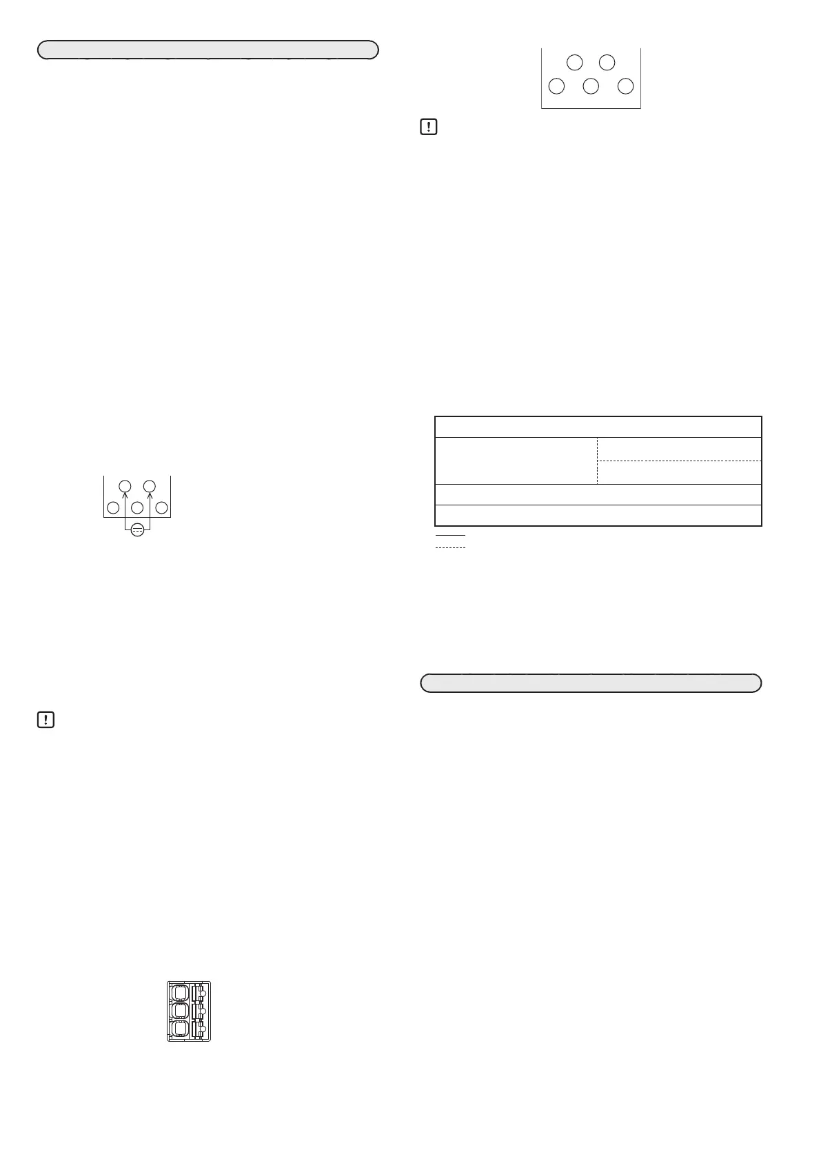
Connecting the power supply
Connect the power terminals as shown below.
1
2
Instrument power supply 24 V DC
4 5 6
The power supply unit must be a Class 2 circuit or limited energy
circuit that has double or reinforced insulation from the main
power.
• Recommended power cable:
Cross-sectional area: 1.25 mm
2
(16 AWG)
Length: 30 m max.
• Terminal lug specifications:
Type: M3 crimp terminal lug
Width: 5.8 mm max.
Tightening torque: 0.6 N·m
Handling Precautions
•
Since linked modules supply power to each other, supply
power to only one of a group of linked modules.
•
Use a power supply that can supply the total power
requirement of the linked modules. The total power
consumption of all connected modules should be no more
than 70 W.
•
If there are multiple wires to the power supply and wiring is
difficult, add a relay terminal or the like.
Connecting to the LAN1 and LAN2 connectors
Insert an RJ-45 connector into the LAN1 connector on the de-
vice. The side connectors on the base are LAN2 connectors.
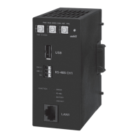
Connecting to RS-485 CH1 and CH2
Connect wires to the RS-485 CH1 connector as shown below.
SG
DB(−)
Connect wires to the RS-485 CH2 terminals as shown below.
1
2
4
5 6
Handling Precautions
•
Terminating resistors are not built into the NX-SVG.
•
0.5W or greater terminating resistor of 150Ω ±5% at each
end of the communications lines. However, if any device that
does not allow a terminating resistor is connected to the
same communications line, follow the instructions on that
device.
•
Be sure to connect the SG terminals to each other. Failure to
do so might cause unstable communications.
•
For communications wiring, use twisted pair cables.
USB host connector
Insert a USB flash drive to save or load data. Do not insert a
device other than a USB flash drive. Attach the USB dust cover
when the USB port is not in use.
I/O isolation
The solid line indicates isolation from other circuits.
Power supply (including side connector)*
1
Logic circuit
Indicators (LED, switch, etc)
USB host communication
RS-485 CH2 communication*
2
LAN2 Ethernet communication*
1
RS-485 CH1 communication
LAN1 Ethernet communication
Isolated
Functionally isolated*
3
*1. The power and LAN2 Ethernet communication circuits connected
to the side connector are isolated from each other.
*2. The RS-485 CH2 communication circuit is not connected to the
side connector.
*3. Dielectric strength is not specified for functionally isolated circuits.
The main purpose of this type of isolation is to improve noise
protection.
SETTING
Smart Loader Package
To set up this device, the SLP-SVG Smart Loader Package (sold
separately) is needed.
Connecting to a PC
This device can be connected to a PC (running the Smart Loader
Package) via Ethernet. Operating environment setup, such as
changing the IP address of the PC, is necessary for connection.
 Loading...