IQ Switch
®
ProxSense
®
Series
Copyright © Azoteq (Pty) Ltd 2022 IQS227-228BEV02 Evaluation Kit User Guide Page 1 of 10
All Rights Reserved Revision 1.0 November 2022
IQS227/8BEV02 User Guide
IQ Switch
®
- ProxSense
®
Series
Table of Contents
1 Introduction .............................................................................................................................. 1
2 Standalone/Data Streaming EV-Kit .......................................................................................... 1
2.1 Overview of module boards .............................................................................................. 2
3 Standalone Operation .............................................................................................................. 2
3.1 Powering on the device .................................................................................................... 2
3.2 Jumper placement ............................................................................................................ 3
3.3 Device operation .............................................................................................................. 3
4 Data Streaming Operation ....................................................................................................... 4
4.1 Setup for data streaming on computer .............................................................................. 4
4.2 Using the GUI with the IQS227B IC .................................................................................. 4
4.3 Using the GUI with the IQS228B IC .................................................................................. 7
4.4 Configuring the IQS227B and IQS228B ............................................................................ 8
5 Communications Interface ....................................................................................................... 8
6 Reference Designs .................................................................................................................. 9
1 Introduction
This user guide describes the operation of the IQS227-228BEV02 Evaluation Kit. The EV-Kit
consists of ten parts, the main board device, six separate plug-in module boards and three
overlays. Additional unprogrammed IC’s (3 x IQS227B and 3 x IQS228B) are included. To
visualise raw data from the EV-Kit, the main board can be interfaced to any personal computer
with USB support, and IQS227 or IQS228 software GUI (Graphical User Interface). The purpose of
the IQS227-228BEV02 EV-Kit is to help application and development engineers in evaluating the
IQS227B and IQS228B proximity and touch sensor in self-capacitance mode.
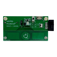
2 Standalone/Data Streaming EV-Kit
Figure 2.1 illustrates the evaluation kit main board and a plug-in module board.
Figure 2.1 IQS227B/228B main board with plugged in IQS228B module board