1: OPERATING AREA AND CONDITIONS
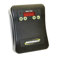
The Bacharach MGS-250 is an instrument for the
connuous monitoring of refrigerant gases.
The instrument is powered by 24V AC or DC. The
output signal can be selected as either voltage or
current. The on-board relay can be used to switch
alarm devices.
2: SAFETY INSTRUCTIONS
USER MANUAL: Before using this equipment,
carefully read and strictly follow the User Manual
(part number 6490-9000). The user must fully
understand and strictly observe the instrucons.
Use the equipment only for the purposes listed and
under the condions specified in those documents.
CODE COMPLIANCE: Comply with all local and
naonal laws, rules and regulaons associated with
this equipment.
GENUINE PARTS: Use only genuine Bacharach spare
parts and accessories, otherwise proper funconing
of the equipment may be impaired.
TECHNICIAN USE ONLY: This unit must be installed
by a suitably qualified technician who will install this
unit in accordance with these instrucons and the
standards in their parcular industry/country. Opera-
tors of the unit should be aware of the regulaons
and standards in their industry/country for the
operaon of this unit. These notes are only intended
as a guide and the manufacturer bears no responsi-
bility for the installaon or operaon of this unit.
Failure to install and operate the unit in accordance
with these instrucons and with industry guidelines
may cause serious injury including death and the
manufacturer will not be held responsible in this
regard.
SAFE MOUNTING: This monitor must be connected
by a marked, suitably located and easily reached
switch or circuit-breaker as means of disconnecon.
WARNING: Strictly follow the
instrucons in the Gas Detector
Manual (part number 6490-9000)
available at www.MyBacharach.com.
CAUTION: DO NOT MOUNT the
MGS-250 in an area that may
contain flammable liquids or
vapors. Operaon of electrical
equipment in such an area cons-
tutes a safety hazard.
GAS DETECTOR
INSTALLATION GUIDE
3: SPECIFICATIONS
To open the housing as received use a flat blade
screwdriver and depress the top latch. While push-
ing the latch, grasp the back edge of the housing
near the latch and pull the back away.
4: MOUNTING
Sensor
Housing
6.3 oz
4.0” x 5.5” x 1.5”
180 g
102 x 140 x 37 mm
Weight
and
Dimensions
Temperature
Rating
-22° to 104° F
-30° to 40° C
Enclosure
ABS plastic; UL ammability
rating of 94V-0
Approvals CE, UL/CSA/IEC/EN 61010-1
NOTE: When installed in areas that may be
subjected to water spray, the oponal splash
guard (P/N: 6900-0001) should be used in
conjuncon with the MGS-250. Weight and
dimensions (above) do not include oponal
splash guard.
When mounted, the housing is simply opened by
pressing the top latch with a suitable screwdriver or
other flat blade. With the top latch depressed pull
the housing apart by grasping the sides and pulling
straight out. With the housing separated the
mounng base with terminal blocks will be visible.
IMPORTANT: Do not apply caulking or
other material around the gas detector
base. The gas detector relies on air
exchange through the spaces between the
base and the gas detector housing. Do not
obstruct the small gap around the housing
and the base with any material.
ACCESSIBILITY: The mounng locaon of the moni-
tor should allow it to be easily accessible for visual
monitoring and servicing.
VIBRATION FREE LOCATION: Do NOT mount the
MGS-250 directly to vibrang machinery as the
vibraons may degrade the gas detector’s perfor-
mance.
PLACEMENT GUIDELINES: The MGS-250 should be
installed plumb and level and securely fastened to a
rigid mounng surface.
WATER SPRAY: When installed in areas that may be
subjected to water spray, the oponal splash guard
(P/N: 6900-0001) should be used in conjuncon with
the MGS-250.
ENVIRONMENTAL CONSIDERATIONS: Carefully
consider the full range of environmental condions
to which the instruments will be exposed.
TARGET GAS CONSIDERATIONS: The physical data of
the gas or vapor to be detected must be observed.
APPLICATION CONSIDERATIONS: The specifics of
the applicaon (for example, possible leaks, air
movement/dra, etc.) must be observed.
ACCESSIBILITY CONSIDERATIONS: The degree of
accessibility required for maintenance purposes
must be granted.
ACCESSORY CONSIDERATIONS: The types of
oponal and accessory equipment that will be used
with the system must be kept in mind.
ELECTRONIC CONSIDERATIONS: The system contains
sensive electronic components that can be easily
damaged. Do not touch nor disturb any of these
components.
Mount the MGS-250 according to the above consid-
eraons, product dimensions (see Secon 3), maxi-
mum wiring lengths (see Secon 5), and the corre-
sponding mounng dimensions shown in the illustra-
ons that follow.
STEP 1: Open the housing.
STEP 2: Posion the base to the pre-determined
(acceptable) mounng locaon. Use the gas detec-
tor base to mark the mounng locaons as needed.
The hole paern on the back plate is sized to mount
the gas detector onto various electrical juncon
boxes. The other holes may be used as needed to
mount the gas detector to other structures, or onto
a wall.
STEP 3 - FOR WALL MOUNT: Aach the MGS-250
base to the mounng surface using two #6 screws
(provided) through two of the mounng holes, being
careful not to over-ghten the screws.
STEP 3 - FOR JUNCTION BOX MOUNT: Aach the
MGS-250 base to the juncon box (using mounng
hardware provided with your juncon box) through
the two juncon box holes.
STEP 4: Unless you are ready to wire the device,
carefully snap the cover onto the base unit.
P/N: 6490-9004
Revision 0
January 25, 2016
4: MOUNTING (CONTINUED) 4: MOUNTING (CONTINUED)
Flat Surface
Mounng Holes
(6 Places)
NOTE: Use #6
screw or smaller for
wall mounng.
Juncon Box
Mounng
Holes (2 Places)
Cable Gland
(Oponal) or
Blanking Plug
(Not Shown)
Cable Gland
(Installed)
DO NOT apply caulking or sealant on or
around the MGS-250 or its base.