Programming the decoder
PLEASE NOTE that except for allocating address and
direction, the standard E-Z C
OMMAND
®
system is unable to
program decoder CVs. A more advanced system, such as
Bachmann’s DyNAMis
®
WirElEss DigitAl COMMAND
C
ONtrOl is required to program decoder CVs.
The locomotive address, acceleration and deceleration
delay, and all other features of the locomotive decoder can
be changed as often as desired by reprogramming. The
features are "stored" permanently in special locations even
when the operational voltage is switched off. These
l
ocations are called "configuration variables" or simply CV.
The configuration of the variables is done electronically,
which means that it is not necessary to open the locomotive
again after the decoder has been installed.
On delivery, the decoder is programmed for operating with
the basic address 03, 28 speed steps and an internal
speedline. The decoder can be used immediately on
purchase with these basic configurations. All configurations
can, of course, be changed.
Testing the installation on equipment other
than Bachmann E-Z COMMAND
®
.
Place the locomotive on the programming track (without its
housing) and read the address. At the factory, the decoder is
programmed to the address 03. If you have connected the
decoder correctly thus far, you should now be able to read
the address. If you are not able to do so, it is possible that
you made a mistake when connecting the wires. Do not
subject the loco to full-running track power until you obtain the
correct "03" address read-out. Check the wire connections and
change them as required. You should now be able to
send your locomotive on its first test run on your layout.
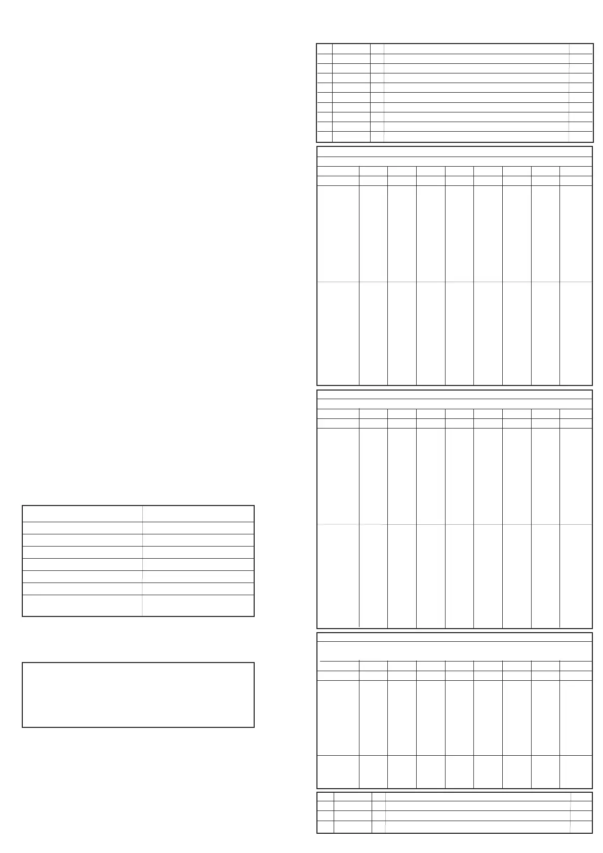
List of supported CVs
Bits are counted beginning with ‘1’
CV Min-Max CV Definition Deft
1 1-99 Locomotive address 3
2 0-31 Starting voltage 10
3 1-255 Acceleration momentum 1
4 1-255 Deceleration momentum 1
7 - Version number 46
8 - Manufacturer ID 101
17 Extended address, high byte 0
18 Extended address, low byte 0
19 1-99 Multi unit (consist) address 0
CV29 - Default value decimal 6
Decoder configuration byte 1
Bit No. 8 7 6 5 4 3 2 1
Default 0 0 0 0 0 1 1 0
Bit = 1
-
-
Decoder uses extended
address CV’s 17/18
-
-
Operation on digital and
analog
28/128 speed steps
Operates with reverse
direction
Bit = 0
-
-
Decoder uses CV1 value
as address
-
-
Digital operation only
14/27 speed steps
Operates with normal
direction
CV50 - Default value decimal 4
Decoder configuration byte 2
Bit No. 8 7 6 5 4 3 2 1
Default 0 0 0 0 0 1 0 0
Bit = 1
-
-
-
-
-
Slows with brake momentum
(set in CV4) if DC on track
when CV29 is set for DCC only
-
-
Bit = 0
-
-
-
-
-
Does not operate if DC on track
when CV29 is set for DCC only
-
-
CV51 - Default value 0
The bit set corresponds to the Function button F1 to F8 to switch output to the
dimmed value (CV52). If set to 0 the output can be switched on/off with F0
Bit No. 8 7 6 5 4 3 2 1
Default 0 0 0 0 0 0 0 0
Bit = 1
Function output dimmed
by F8
Function output dimmed
by F7
Function output dimmed
by F6
Function output dimmed
by F5
Function output dimmed
by F4
Function output dimmed
by F3
Function output dimmed
by F2
Function output dimmed
by F1
Bit = 0
-
-
-
-
-
-
-
-
52 0 - 255 Dimming F-output A, 0 is dark 255 is max brightness 64
Function output dimming
0 Dark
255 Maximum brightness
Printed in China
Technical Data
Normal operation:
current carrying capacity
of the decoder in sum 1 A
motor output 1 A
function output 100 mA
addresses 1 - 9999
speed steps 14, 27, 28, 128
dimensions 16 x 25 x 5mm
Reset to Factory Settings
You can reset this decoder to factory
default settings by setting configuration
variable 8 (CV8) to a value of 8 using any
NMRA-compliant DCC controller.
H4913-IS002
 Loading...