Do you have a question about the Baileigh RDB-250 and is the answer not in the manual?
Buyer's process for inspecting and accepting goods, including returns.
Seller's right to make changes to product specifications.
Seller's warranty terms, exclusions, and limitations for the product.
Explains the safety alert symbol and the importance of following precautions.
Defines DANGER, WARNING, and CAUTION signal words used for hazards.
Advises wearing safety glasses and hearing protection.
Warns about crush points in the die area and pinch points.
Keep clear of moving objects, hydraulic hose failure, and high voltage areas.
Maintain clean area, dress appropriately, use PPE.
Avoid overloading, forcing, use right tools, ensure proper setup.
Stay alert, avoid alcohol/drugs, check for damage, observe conditions.
Do not touch live parts, turn off power, grounding, and interlocks.
Keep visitors at a safe distance from the work area.
Considerations for leveling, floor, working clearances, and power placement.
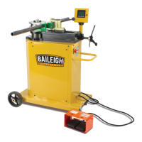
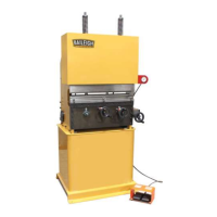
Identifies and describes the function of key machine components labeled A through N.
Details the voltage, frequency, and current requirements for the machine's motor.
General electrical connection considerations and safety advice.
Guidelines for selecting and using appropriate extension cords.
Steps for properly connecting the machine's power plug.
Introduces the fully programmable touch screen interface for creating and saving bends.
Steps for powering on the machine and its initial homing procedure.
Explains the touch screen display layout and the function of various keys.
Guides on navigating the main menu to run, view, or edit programs.
Detailed steps for modifying existing bend programs.
Instructions on how to erase bend data for a selected program.
Steps for creating new bend programs from scratch.
Continued steps for naming, saving, and entering parameters for new programs.
Step-by-step guide to executing a programmed bend sequence.
How to perform bends to specific angles without programming.
Describes bending to any angle controlled solely by the operator.
Visual examples of various OEM screen displays.
How to accurately lay out material for bending, including formulas and diagrams.
Specific advice for bending aluminum, including lubrication and material types.
Suggestions for bending heavy wall DOM tubing to prevent slipping.
Step-by-step guide to setting up square tooling for bending operations.
Tips for bending large square tubing, including counter die positioning.
Steps for connecting the indexing table to the bending machine.
Guidance on adjusting the index table's height and ensuring it is level.
How to lay out material for use with the indexing table.
Instructions for operating the indexing table to set stops and make bends.
Specifics on the type and frequency of gear box oil changes.
Instructions for lubricating the main spindle bearing.
A chart detailing standard pipe sizes, OD, and wall thickness schedules.
A chart explaining the color coding used for different die materials.
A table providing constants for calculating arc lengths based on bend degrees.
An exploded view of the machine's base assembly components.
An exploded view of the components within the control box.
An exploded view of the machine's drive assembly components.
An exploded view of the main bending assembly components.
| Brand | Baileigh |
|---|---|
| Model | RDB-250 |
| Category | Power Tool |
| Language | English |