Do you have a question about the Baileigh SF-5216E and is the answer not in the manual?
Understanding safety alert symbols, signal words (DANGER, WARNING, CAUTION) for hazard identification.
Contact information and services provided by the technical support department for setup, warranty, and parts.
Instructions for cleaning the machine, including warnings about specific cleaning agents and rust prevention.
Guidelines for securing the machine to the floor, specifying concrete thickness and anchoring methods.
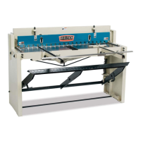
Attaching the foot pedal to the shear frame, showing the finished assembly.
Instructions for attaching front extension rails using hex bolts and flatwashers.
Steps for installing rear gauge shafts, micro-adjustment assemblies, and the stop angle.
Explains the dual function of the foot pedal: lowering hold downs and activating the shear blade.
Describes the purpose of front extensions for material support and rear extensions for micro-adjusters.
Details how the rear stop angle is used for precise dimensioning in repetitive shearing.
Explains the adjustability of the front stop and push plate for positioning and angle shearing.
Steps for using the miter angle guide for angled cuts by positioning against the straight edge.
How to attach material support arms to the front of the shear for supporting large pieces.
Details how adjustable stops are used for accurate placement and setting of the stop angle.
Advice for achieving best results, including material width vs. thickness and blade gap settings.
A chart providing thickness equivalents for various materials based on gauge and tensile strength.
Table showing recommended blade gap settings based on metal thickness.
Table listing materials, their shear strength (tons/sq. in.), and a factor for calculating thickness.
Procedure for adjusting the hold down to secure the workpiece and prevent finger injury.
Method for adjusting gibs to remove unwanted slide movement and prevent binding or wear.
Steps for adjusting blade alignment and contact, ensuring proper cutting.
Information on removing, sharpening, and replacing shear blades.
Daily checks for unsafe conditions, securing bolts, and keeping the work area clean.
Weekly tasks including cleaning, applying rust inhibitor, lubricating parts, and checking guards.
| Max Cutting Width | 52 inches |
|---|---|
| Max Material Thickness | 16 gauge |
| Mild Steel Capacity | 16 gauge |
| Back Gauge Range | 0-24 inches |
| Phase | Single |
| Blade Length | 52 inches |
| Max Cutting Capacity | 16 gauge (mild steel) |