Do you have a question about the Baker Hughes 2000 Series and is the answer not in the manual?
Lists the key features and benefits of the Electrospeed Advantage drive, covering connectivity, expandability, and operational advantages.
A step-by-step guide for the initial setup and testing of the variable speed drive.
Covers essential safety recommendations, procedures, and installation guidelines for the drive.
Guidelines for safe installation and servicing by qualified electrical maintenance personnel.
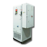
Details on NEMA 4 (IP56) and NEMA 1 (IP30) enclosure configurations available for the drive.
Explanation of the interlock feature on the electrical disconnect handle allowing door opening during operation.
Procedures for safe operation inside cabinets, energy isolation, and capacitor discharge.
Guidelines for securely fastening, immobilizing, and transporting the drive enclosure.
Recommendations for storing the drive to prevent damage from corrosive atmospheres or temperature extremes.
Guidance on selecting appropriate installation locations for NEMA 1 and NEMA 4 enclosures, considering ventilation.
Pre-installation checks for physical damage, packing materials, compatibility, and internal connections.
Instructions for power and control wiring, grounding, cable routing, and terminal connections.
How to configure and use the category zero emergency stop option for de-energizing the drive.
Using 12 or 24-pulse converter configurations to minimize harmonic distortion on the power system.
Overview of the two different system control circuit boards used in Advantage drives.
Explains the function of each keypad switch (START, STOP, Arrow Keys, ENTER, MENU) on the operator interface.
Describes the meaning of the green, amber, and red panel lights indicating motor status.
Details the capacitive touch keypad operation, including a start/stop delay and temperature range.
Explains the function of the key switch for disabling keypad operations.
Describes the two sets of indicator lights and their operational states.
Details the specific states indicated by the built-in green, amber, and red LEDs.
Explains how to connect and configure optional external panel lights for status annunciation.
Explains how the drive selects between internal Hand and Auto operational modes.
How to configure and use external HOA and Start switches for drive operation modes.
How a manual keypad lockout shutdown is annunciated and cleared.
How to navigate menus, view parameters, and interpret screen information.
Explains the symbols and graphics used in drive menus and screens for information conveyance.
Step-by-step guide on how to edit parameters using the drive's interface.
How to configure and use system security to guard against unauthorized set point editing.
How the drive uses a battery-backed real-time clock for time-keeping and event stamping.
Provides functions for managing status parameters, custom user screens, and screen captures.
How the drive uses USB flash drives to record and restore system configurations.
Verifies and adjusts the real-time clock settings for accurate event logging.
Selects the system language and measurement units (imperial/metric).
Selects the input method for drive configuration, such as using an AutographPC File.
Enters descriptive site names and optional notes for location identification.
Verifies or enters the detected power system voltage and frequency.
Enters motor parameters using manufacturer's nameplate ratings.
Enters downhole cable size, type, length, and well temperature.
Sets operating frequency, high speed clamp, and low speed clamp limits.
Summarizes transformer parameters and allows editing of selected values.
Finalizes the setup sequence or directs the user to the Easy I/O Setup.
Configures analog input devices, including signal type, scaling, and threshold alarms.
Assists in configuring digital or status inputs to the drive, including alarm and lockout settings.
Configures internal signals or events to annunciate status via digital outputs, for alarms or shutdowns.
Describes the five status or digital inputs and their pin-out definitions.
Describes the five digital outputs, often used for panel lights, and their pin-out definitions.
Accesses parameters for the 0-10 VDC or 4-20 mA signal applied to Analog Input Terminal 1.
Accesses parameters for a high threshold alarm on Analog Input 1.
Accesses parameters for a low threshold alarm on Analog Input 1.
Provides a visual overview of the drive's menu organization and navigation.
The primary operator display for viewing drive parameters and status information.
Gathers parameters needed to start up and run the drive, organized into five screens.
Configures parameters for starting and running the drive, including frequency settings.
Parameters for operating in Torque Control mode, calculating motor and shaft RPM.
Enters descriptive site names and optional notes for location identification and protection settings.
Accesses screens for configuring the optional Electrospeed Input Electrical Filter.
Lists available software algorithms that can be enabled and utilized.
Controls automatic restart parameters, counters, and delay settings.
Provides access to recorded history stored within the Advantage drive.
Accesses data logging functions using a non-volatile memory card for recording data.
Copies internal history databases to the CF card in CSV format for analysis.
Saves drive settings to a Compact Flash card for archiving or recreating configurations.
Restores a previously saved setup or configuration from the CF Card.
Allows transfer of software updates and historical data to and from the USB port.
Retrieves and utilizes configuration settings from a file created by Autograph PC software.
Reprograms drive parameters using settings stored on a USB mass storage device.
Enters descriptive site names and optional notes for location identification.
Gathers available graphing functions, including amp charts.
Provides access to motor and drive protection features and alarm condition setups.
Protects the motor from excessive current draw by monitoring output current.
Protects the motor from insufficient current draw, often indicating low fluid volume.
Monitors three output currents and causes a shutdown if unbalance exceeds the user set threshold.
Protects the drive from stresses resulting from excessive input voltage.
Detects and annunciates power supply problems related to undervoltage conditions.
Detects and annunciates power supply problems related to voltage unbalance.
Protects the motor from operating below a user-selected frequency for longer than the specified time delay.
Provides access to parameters for temperature sensors built into the Advantage drive.
Alarm for when a valid message is not received within associated time delays.
Enables or disables many alarm conditions within a single screen for user convenience.
Provides access to programmable functions, including control algorithms and user-defined alarms.
Offers multiple modes of output speed control, such as Frequency Setpoint, Analog Follower, PID, and MaxPoint.
Varies output frequency based on analog input signal for proportional control between set limits.
Varies output frequency to maintain a given feedback (analog input) signal using PID control.
Optional software algorithm to clear gas locks and manage drawdowns in challenging wells.
Provides user access to execution control blocks for creating custom programmable logic functions.
Accesses user database points for calculations and logical functions, allowing point ID editing.
Provides access to eight configurable alarms for motor shutdown based on defined conditions.
Allows use of output relays to annunciate alarms or shutdowns, connecting to control systems or lamps.
Selects an analog input signal or source to drive an analog output on Expansion I/O Modules.
Reorganizes data in widely separated address locations into contiguous blocks for SCADA/monitoring.
Configures a closed-loop control system utilizing analog inputs and outputs for PID control.
Provides a user-configurable display screen by copying parameters from other screens.
Accesses system maintenance, security, and communication options within the Advantage drive.
Groups parameters controlling communications to external computer systems and telemetry devices.
Provides access to configuration screens for the two Ethernet ports.
System status variable annunciating SCADA or User PLC motor shutdown command.
Accesses system security features of the Advantage drive, including password settings.
Displays and allows resetting of the battery-backed real-time clock.
Displays input/output current, voltage, power, and accumulated power consumption.
Utilizes converter sections to minimize harmonic distortion, measuring phase B current.
Displays input voltage measurements, considering filter effects.
Displays instantaneous power consumption of the drive.
Displays output AC voltage, current, kW, kVA, and power factor.
Displays transformer output voltages and motor voltages based on drive settings.
Allows access to submenus for controlling setup parameters of Input/Output Modules.
Provides access to setup screens for built-in I/O (analog inputs, digital inputs/outputs).
Accesses parameters for the 0-10 VDC or 4-20 mA signal applied to Analog Input Terminal 1.
Accesses parameters for Analog Input 2, similar to Analog Input 1.
Accesses parameters related to digital status signals applied to terminals.
Permits user access to digital output relays configured as general purpose outputs.
Shows status of additional input/output ports available on the Advantage drive.
Accesses parameters related to installed expansion input/output modules.
Enables expansion modules and monitors CITIBus communication success rate.
Displays error, timeout, and CRC rates for all installed modules.
Lists the technical specifications and operational ratings for the Advantage VSD.
Provides a template for recording installation and service details of the VSD.
Details historical logging capabilities common to Advantage Series VSDs.
Lists standards met and certification marks for the Electrospeed Advantage™ Variable Speed Drive.
Explains the 24 pulse input converter configuration for minimizing harmonic distortion.
Setup of Advantage VSDs with FPWM™ capability applied on Electrical Submersible Pumps.
Provides model designations and variable torque VSD ratings.
Provides recommended cable sizing and input fuse information for NEMA 4/IP56 drives.
Illustrates control schematic diagrams for various Advantage drive series and configurations.
Provides power schematic diagrams for Advantage drive series, detailing component connections.
Provides outline and anchor dimensional diagrams for various Advantage drive models.
| Brand | Baker Hughes |
|---|---|
| Model | 2000 Series |
| Category | Inverter |
| Language | English |