Do you have a question about the Baker Hughes Masoneilan SVI3 and is the answer not in the manual?
Defines WARNING, CAUTION, and NOTE symbols used for safety.
Provides safety instructions for the SVI3 digital valve positioner.
Information on the purpose and conventions used in the SVI3 Instruction Manual.
Lists other documentation and contacts for SVI3 related information.
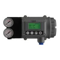
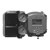
General description of the SVI3 digital valve positioner and its capabilities.
Lists the key features and capabilities of the SVI3 Digital Valve Positioner.
Details the physical housing and operational principles of the SVI3 positioner.
Information on using ValVue software for setup, monitoring, and diagnostics.
Overview of the diagnostic capabilities offered by the SVI3.
Provides physical dimensions and weight specifications for the SVI3.
Key guidelines to follow before starting the installation process.
Outlines the procedures for installing the SVI3 positioner.
Instructions for mounting the SVI3 on rotary and reciprocating actuated valves.
Procedure for connecting pneumatic tubing and air supply to the SVI3.
Guidelines and practices for wiring the SVI3, including explosion-proof installations.
Instructions for connecting the SVI3 to the control loop wiring.
Procedure for wiring the optional SVI3 options board.
Details on making Digital Input (DI) connections to the SVI3.
Description of the SVI3's two digital output switches and their configuration.
Information on configuring the digital output switches of the SVI3.
Instructions for connecting a remote position sensor to the SVI3.
Instructions for connecting the 4-20mA retransmit output.
Instructions for connecting a 1-5V process variable input.
Guidelines for making system connections according to HART specifications.
Ensuring proper grounding for case and signal wiring connections.
Understanding compliance voltage requirements for system operation.
Procedures and considerations for powering up the SVI3 positioner.
Configuration of actuators as Air-to-Open (ATO) or Air-to-Close (ATC).
Checks to perform before initial power-up of the SVI3.
Step-by-step guide for powering up the SVI3 unit.
Introduction to the communication, configuration, and calibration interfaces.
Using ValVue software with SVI3 DTM for advanced control and diagnostics.
Utilizing SVI3 Device Description files with HART communicators.
Basic interface using the SVI3's local display and four pushbuttons.
Detailed steps for configuring and calibrating the SVI3 using ValVue.
Covers the optional local interface using LCD display and pushbuttons.
Functions of the four pushbuttons for navigating menus and adjusting values.
Understanding NAMUR NE 107 status signals for fault indication.
Security features to lock pushbuttons and hardware configuration.
Using a jumper for hardware-based configuration security.
Procedure for initiating the Smart Cal single-button calibration.
Explanation of NORMAL and MANUAL operating modes and menu structures.
Accessing and viewing configuration, calibration, and status information.
Reading and clearing diagnostic error messages from the SVI3.
Procedure for viewing and clearing fault codes and messages.
List and explanation of fault codes that appear on the SVI3 display.
Steps to return the positioner to NORMAL operating mode.
Accessing the menu for configuring SVI3 parameters.
Configuring the relationship between input signal and valve position.
Selecting display units for the actuator pressure sensor (PSI, BAR, KPA).
Description of the Tight Shutoff performance feature.
Access to all calibration functions, including STOPS, TUNE, SIG LOW/HIGH.
Procedure for calibrating the valve travel range using the Find Stops function.
Adjusting the reported 100% position to match nominal valve travel.
Procedure for automatically tuning the SVI3 for optimal valve response.
Setting the input signal range for full valve travel (SIG LO and SIG HI).
Handling critical faults and restarting the valve from a failsafe condition.
Performing checkout and calibration using HART communication.
Overview of the menu structure for HART communication.
Procedure for running the Auto Tune function via HART.
Procedure for running the Find Stops calibration via HART.
Procedure for adjusting open stop calibration via HART.
Procedure for running diagnostic tests via HART.
Viewing and clearing current and historical faults via HART.
Overview of maintenance procedures and repair guidelines for the SVI3.
Instructions and requirements for performing repairs on the SVI3.
List of available spare parts kits for the SVI3.
Information on the SVI3's internal self-diagnostics and hardware checks.
Detailed list of faults, causes, and recommended actions for SVI3 diagnostics.
Details the physical and operational specifications for the SVI3.
Guidelines for storing the SVI3 to prevent damage.
Information on the protective measures applied to the SVI3 during shipping.
Precautions and care to be taken when handling the SVI3 positioner.
Instructions for the safe and environmentally sound disposal of the SVI3.
Explanation of how to interpret the SVI3 model number.
Compares models and features of SVI3 regarding diagnostic levels.
Adjusting tuning parameters to control the speed of response.
Details on the Aggressiveness parameter and its effect on tuning.
Steps and tips for troubleshooting issues with the Autotune function.
Description of the Tight Shutoff feature for preventing valve seat damage.
Examples of using SVI3 DTM for advanced valve diagnostics.
Overview of the SVI3's online valve diagnostics suite for performance monitoring.
Using the Valve Health tab in DTM for real-time KPI data access.
Using historical trend views in DTM for KPI analysis.
Configuring alerts and limits for SVI3 KPIs to monitor performance.
Definitions and use cases for various Valve Health Key Performance Indicators.
Explains how to determine the necessary compliance voltage for SVI3.
Procedure and setup for testing compliance voltage requirements.
Requirements for HART compliant communication loops.
Configuration for split range applications supporting multiple valves.
Using Intrinsic Safety Isolators for HART circuits in split range applications.
Boosting DCS compliance voltage using a supplemental power supply.
Procedure to ensure SVI3 split range system is properly powered.
Wiring considerations for successful HART communication in hazardous areas.
Ensuring intrinsic safety barriers are designed for HART signal transmission.
Considerations for signal circuit design regarding output channel isolation.
| Type | Digital Valve Positioner |
|---|---|
| Input Signal | 4-20 mA |
| Output Signal | Pneumatic |
| Communication Protocol | HART |
| Materials | Aluminum, Stainless Steel |
| Supply Pressure | 20 to 100 psi |
| Operating Temperature | -40 to 85°C (-40 to 185°F) |
| Enclosure | IP66/NEMA 4X |
| Mounting | Direct mount to rotary or linear actuators |