Do you have a question about the Baker Hughes Masoneilan SVIII AP and is the answer not in the manual?
| Brand | Baker Hughes |
|---|---|
| Model | Masoneilan SVIII AP |
| Category | Valve Positioners |
| Language | English |
Defines safety symbols used in the manual.
Describes the ValVue software and its capabilities for the SVI II AP.
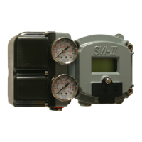
Lists the key features and capabilities of the SVI II AP.
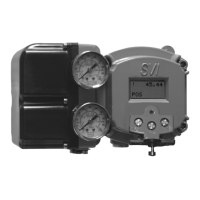
Explains the basic operation of the SVI II AP positioner.
Guides on downloading and installing ValVue3 software.
Introduces the installation and setup procedures for the SVI II AP.
Outlines the sequential steps for installing the SVI II AP.
Details checks and procedures to perform before powering up the SVI II AP.
Explains the procedure for mounting the SVI II AP onto the actuator.
Provides instructions for mounting the SVI II AP on rotary valve actuators.
Explains how to orient the magnet on rotary valve shafts for proper function.
Provides instructions for mounting the SVI II AP on reciprocating valve actuators.
Guides on connecting pneumatic tubing and air supply to the SVI II AP.
Outlines the procedure for wiring the SVI II AP.
Explains how to connect the SVI II AP to the control loop via HART.
Lists the physical and operational checkout procedures for the SVI II AP.
Describes methods to visually inspect or use ValVue to check the magnet.
Procedures to check the air supply for leaks and proper pressure.
Verifies all applicable connections to the electronics module.
Details the steps for operational checkout of the SVI II AP.
Step-by-step instructions for powering up the SVI II AP.
Introduces the digital interfaces for communicating, configuring, and calibrating the SVI II AP.
Details the use of the local display and pushbuttons for operation.
Describes the functionality of the HART handheld communicator.
Explains the use of ValVue software for configuration and calibration.
Describes the normal and manual mode menu structures.
Guides users through the configuration menu options.
Provides access to all calibration functions for the SVI II AP.
Details how to handle and exit the failsafe mode.
Provides procedures for viewing, configuring, and calibrating the SVI II AP.
Offers guidance on troubleshooting the autotune feature if it fails.
Step-by-step guide for calibrating the SVI II AP via pushbuttons.
Details the procedure for auto-tuning the SVI II AP.
Guides on adjusting the input signal range for calibration.
Introduces wiring configurations for HART digital communications.
Outlines system connection requirements compliant with HART protocol.
Provides guidelines for successful implementation of DC current signal and HART communication.
Details compliance voltage requirements for single drop current mode.
Explains considerations for operating the SVI II AP in split range configurations.
Details when a HART filter is required for control system output circuits.
Explains proper grounding procedures for case and signal wiring.
Discusses wiring considerations for intrinsic safety in hazardous areas.
Explains the design requirements for intrinsic safety barriers transmitting HART signals.
Details HART filter requirements for control system output circuits.
Explains the electro-pneumatic digital valve positioner's operating principle.
Outlines recommended maintenance and repair procedures.
Explains the repair-by-replacement method for servicing the SVI II AP.
Details the SVI II AP's internal self-diagnostics and hardware checks.
Explains how the SVI II AP enters and operates in FAILSAFE mode.
Lists environmental operating and storage specifications.
Details operational specifications like accuracy, hysteresis, and flow characteristics.
Lists HART device information, model names, and protocol revisions.
Details device variables returned via HART command 9.
Explains the importance of assigning actuator action (ATO/ATC) correctly.
Warns about explosion hazards due to improper installation in natural gas environments.
Discusses connecting remote vent gas piping for actuator venting.
Emphasizes the importance of a high-quality air supply and safe failure conditions.
Explains how to adjust the control valve's speed of response using calibration software.
Describes using Tight Shutoff to prevent valve seat erosion.
Explains how to use Tight Shutoff for high pressure liquid letdown valves.
Illustrates uses of ValVue for diagnostics like continuous monitoring.
Explains standard diagnostic tests like full stroke and step response.
Defines accuracy in the context of control valve position.
Defines an actuator and its types.
Defines an algorithm in the context of SVI II AP operation.
Defines the Air to Close actuator action.
Defines the Air to Open actuator action.
Defines the CALIBrate mode of the positioner.
Defines the relationship between setpoint and valve position.
Defines the voltage required to drive control current through the system.
Defines technology for predicting maintenance needs.
Defines the CONFIGure mode of the positioner.
Defines the custom characteristic option for valve control.
Defines the tools for monitoring internal condition and performance.
Defines a double acting actuator.
Defines a valve characteristic for pressure compensation.
Defines error messages stored by the positioner.
Defines the failsafe mode of the positioner.
Defines a non-recoverable error requiring service.
Defines a sensor measuring magnetic flux.
Defines a filter for non-HART compliant DCS systems.
Defines an area with explosion hazards.
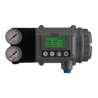
Describes the SVI II AP High Flow positioner.
Explains Mean Time To Repair using ValVue for configuration.
Defines the current-to-pressure converting device.
Defines the normal control mode for valve positioning.
Defines how to set predetermined stop positions via software.
Explains the six integer parameters for positioner response tuning.
Defines a control configuration for multiple valves.
Defines the procedure to adjust positioner to actual valve travel.
Defines a property to prevent operation near the closed position.
Defines Masoneilan software for diagnostics, calibration, and configuration.
Defines a mode to examine configuration and calibration parameters.
Defines a mode to examine error status or messages.
Explains the HART Burst mode for devices incapable of being polled by a Master.
Lists faults, types, causes, and resolutions for device status.
Defines compliance voltage and its importance in control systems.
Details the setup for performing a compliance voltage test.
Lists initial tasks for configuring and using the SVI II AP DTM.
Lists common tasks performed at any time using the SVI II AP DTM.