EasyManua.ls Logo

Baker Instrument Company D12000 - User Manual

Default Icon
24 pages
Print Icon
To Next Page IconTo Next Page
Loading...
1
Baker Instrument Company
The Measure of Quality
DIGITAL TROUBLESHOOTING PROCEDURES
&FAULT LISTING
1. Knurr case removal.
2. Rittal case removal.
3. A/D board, I/O board, and controller board access instructions.
4. Voltage Busline and Crystal Checkout.
5. Open Ground fault indicator lamp lit.
Open Ground circuit disable instructions for 6kV, 12kV, 24kV, D-Series
testers.
6. Hipot Trip fault indicator lamp lit.
7. Hipot Current Bar display not present.
8. CRT blank when PTT button depressed/surge mode.
9. Hipot voltage bar display not present.
10. Seconds/div, volts/div, µA/div, or function display incorrect.
11. Printer does not work properly.
12. No Baker logo displayed.
13. No Hipot voltage at test leads.
14. No surge voltage display.
15. Voltage drops when PTT button released.
16. Zero Start Interlock does not engage.
17. PI Value or current measurement inconsistent.
18. Display locked up after self-test.
19. Display unreadable and flashes on/off, does not initiate self-tests.
Question and Answer IconNeed help?

Do you have a question about the Baker Instrument Company D12000 and is the answer not in the manual?

Summary

Knurr Case Removal

Rittal Case Removal

A;D Board, I;O Board, and Controller Board Access Instructions

Voltage Busline and Crystal Checkout

Open Ground Fault Indicator Lamp Lit

Open Ground Circuit Disable Procedure

Procedure to disable the open ground fault detection for 6kV, 12kV, 24kV D Series testers.

Hipot Trip Fault Indicator Lamp Lit

Hipot Current Bar;Display Not Present

CRT Blank When PTT Button Depressed;Surge Mode

Hipot Voltage Bar;Display Not Present

Seconds;Div, Volts;Div, µA;Div or Function Display Incorrect

Printer Does Not Work Properly

No Baker Logo Displayed

No Hipot Voltage at Test Leads

No Surge Voltage Display

Voltage Drops When PTT Button Released

Zero Start Interlock Does Not Engage

PI Value or Current Measurement Is Inconsistent

Display Locked Up After Self-Test

Display Unreadable and Flashes On;Off, Does Not Initiate Self Test

A;D Board, I;O Board, Controller Board Access Instructions

ECO Record

Overview

This document outlines troubleshooting procedures and a fault listing for a Baker Instrument Company digital series tester, focusing on models like the 6kV, 12kV, and 24kV D-Series. The manual details various issues that can arise and provides step-by-step instructions for diagnosis and repair, including physical access to internal components, electrical checks, and component replacement.

Function Description:

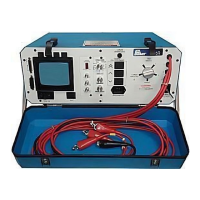
The Baker digital series tester is designed for electrical testing, specifically performing Hipot and Surge tests. It features a CRT display for visualizing waveforms and numeric readouts for voltage, current, and other parameters. The device incorporates a Power Supply board, A/D board, I/O board, and a Controller board, all working in conjunction to execute tests and display results. It includes controls for function selection (Hipot/Surge), volts/division, seconds/division, µA/division, intensity, and vertical/horizontal position. The tester is equipped with indicator lamps for "Open Ground fault" and "Hipot Trip fault." It also supports printing test results.

Important Technical Specifications:

  • Voltage Busline Supplies: +5 volts, +12 volts, -12 volts.
  • Crystal Frequencies: Multiple crystals on A/D and Controller boards are critical for operation.
  • Line Voltage Ranges:
    • D6000: 100-120 Volts AC
    • D12000: 100-120 Volts AC
    • DS206: 220-250 Volts AC
    • DS212: 220-250 Volts AC
  • Hipot Current Measurement: Ranges include 1µA, 10µA, 100µA.
  • Surge Voltage Display: Settings include 500 volts/division and 6µS/Division.
  • Firmware Revisions:
    • Models before December 1997 (serial #001-370): Firmware 1.35 for Epson FX dot matrix printer.
    • Models after December 1997 (serial #370+): Firmware 1.36 for Epson DeskJet 600 printer.
    • EEPROM IC U3 revision 1.37 for Polarization Index clock, three-surge test patterns recall, and compatibility with Epson 640 inkjet printer and MTA for Windows.
  • Accuracy: Designed to produce results within +/- 5% specifications.

Usage Features:

  • Test Modes: Supports Hipot and Surge testing.
  • Controls: Function knob, volts/division knob, seconds/division knob, µA/division knob, intensity, vertical, and horizontal position knobs.
  • PTT Button: Used to activate tests.
  • Zero Start Interlock: A safety feature that requires the output control knob to be fully counter-clockwise before engaging.
  • Open Ground Circuit Disable: Instructions are provided for 6kV, 12kV, and 24kV D-Series testers to operate in environments without a supplied ground, though the "Open Ground LED" will remain lit. This involves removing jumpers and potentially installing a toggle switch.
  • Test Leads: Equipped with alligator clips for connecting to the test load.
  • Printer Output: Allows for printing test results.
  • Software Compatibility: Firmware 1.37 enables compatibility with MTA for Windows operating software system.
  • Polarization Index Clock: Firmware 1.37 adds a Polarization Index clock that can be reset after the proper test voltage is reached for a full one or ten-minute megohm test.
  • Three-Surge Test Patterns: Firmware 1.37 allows recalling all three-surge test patterns with test voltages for each lead displayed in any summary.

Maintenance Features:

  • Case Removal: Detailed instructions for removing both Knurr (pre-August 1998) and Rittal (post-serial #327) design cases to access internal components.
  • Board Access: Step-by-step guide for accessing the A/D board, I/O board, and Controller board from the front panel.
  • ESD Precautions: Emphasizes that C-MOS logic boards are ESD sensitive and recommends removal at a grounded station with a grounded wrist strap to prevent integrated circuit damage.
  • Troubleshooting Guides: Comprehensive fault listing and troubleshooting steps for various issues, including:
    • "Open Ground fault indicator lamp lit"
    • "Hipot Trip fault indicator lamp lit"
    • "Hipot Current Bar/Display Not Present"
    • "CRT Blank When PTT Button Depressed/Surge Mode"
    • "Hipot Voltage Bar/Display Not Present"
    • "Seconds/Div, Volts/Div, µA/Div or Function Display Incorrect"
    • "Printer Does Not Work Properly"
    • "No Baker Logo Displayed"
    • "No Hipot Voltage at Test Leads"
    • "No Surge Voltage Display"
    • "Voltage Drops When PTT Button Released" (includes a modification for older models)
    • "Zero Start Interlock Does Not Engage"
    • "PI Value or Current Measurement Inconsistent"
    • "Display Locked Up After Self-Test"
    • "Display Unreadable and Flashes On/Off, Does Not Initiate Self Test"
  • Component Checks: Instructions for checking specific components (e.g., MOVs, SCRs, crystals, ICs, resistors, transformers) using multimeters and oscilloscopes.
  • Power Supply Diagnosis: Method to identify defective Power Supply boards or boards loading a supply by sequentially unplugging I/O, A/D, and Controller boards.
  • Calibration: Notes that I/O board replacement requires calibration, while A/D or Controller board replacements may not.
  • Line Voltage Fluctuation Mitigation: Recommends using a Patriot line conditioner or connecting to an isolated outlet to improve consistency of PI values and current measurements.
  • Engineering Changes (ECO Record): Lists factory-installed improvements for D12000 series after serial number 210, including:
    • CRT cooling fan to prevent scrolling at high temperatures.
    • Power board component changes (R3, C1) for Q1 reliability.
    • Discharge board changes (R5) for improved surge signal shaping.
    • Isolation of surge readout cable and ground routing changes for better noise resolution.
    • Stack board component changes (R1, R34) for SCR reliability.
    • Zero Start Interlock board revision for common neutral/ground design, eliminating false Hipot trips and allowing disablement with a footswitch.
    • Addition of K1 and K2 relays and wiring harness changes to prevent surge voltage drop on CRT when PTT button is released.
    • EEPROM IC U3 firmware updates for enhanced capabilities (Polarization Index clock, three-surge test patterns, printer compatibility).
    • A/D board grounding changes, clamping diodes, and bypass capacitors for IC U14 reliability.

Baker Instrument Company D12000 Specifications

General IconGeneral
BrandBaker Instrument Company
ModelD12000
CategoryTest Equipment
LanguageEnglish

Related product manuals