Page 5 54751_97_B
B
HT
10
10
HTR
G
50
J
10
J7
2
2
1
J2
3
52
51
F6, T30A 480
Z
NE
MP 1
PT. BLWR
P
MP
IR
. P
M
E
E
47
29
2
17/26
20
BALB
A IN
TRUMENT
IN
500Z
PYRI
HT 2006
ADE IN
.
.A.
P/N 22015
60
4
1
7
8
T
T
6
EN
A
EN B
2
J4
13
11
12
J19
1
WIT
HBANK A
8
5
4
3A 250V
2
GS5xxDZ mode
1
7
J6
30
480
-P332
E
P/N 22909 REV B
2-Spd P2
Blower
3.0 kW
Heater rated @ 230V
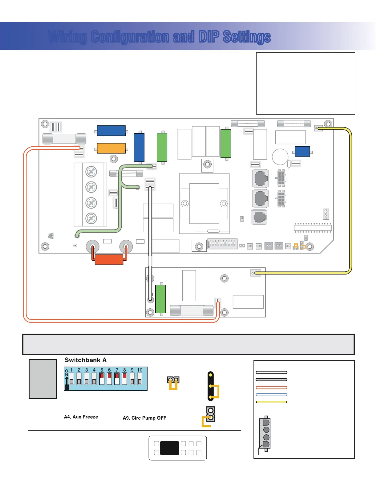
J11 must be Jumpered
3.0kW
Spa
Light
Audio Visual
Circ Pump
DIP switch A9 must be ON if Circ Pump is installed.
Ozone
2-Spd P1
Wiring Configuration and DIP Settings
Setup 1 (As Manufactured)
s 60UMP3PEED
s 60UMP3PEED
s 6"LOWER
s 63PA,IGHT
s 6/ZONE
s 6!<6(Stereo)
s 6K7(EATER
s $ELUXE-AIN0ANEL
s
6#IRC0UMPOPTIONAL
A1, Test Mode OFF
A2, See Table 1
A3, N/A
A7, J17/26 Disabled
A10, See Table 1
A5, NA when A9 if OFF
Panel Button Assignments
1=Time
2=Mode/Prog
3=Temp Up
4=Temp Down
5=Light
6=Pump 1
7=Pump 2
8=Unused
Panel Button Positions
1
2
3
4
8
6
5
7
100
94
39
SSID #
J11
3.0kW
Heater
J12
1
2
3
GS520DZ
Software
Memory
Reset
J43
A8, Degrees C
A7, J17/26 Enabled
8=J17/26
A6, 50 Hz
A5, 2-speed P1
Neutral (Common) AC Connections
Special AC Connections
Line AC Connections
10 Volt Connections
Relay Control Wires
Wiring Color Key
Typically Line voltage
Typically Line voltage for 2-speed pumps
Neutral (Common)
Ground
Note flat sides in connector
Board Connector Key
1
2
3
4
WARNING: Main Power to system should be turned OFF BEFORE adjusting DIP switches.
WARNING: Persistent Memory (J43) must be RESET to allow new DIP switch settings to take effect. (See Persistent Memory page)
HIPot Testing Note:
Disconnect slip terminal with green
wires from J90 prior to performing
HiPot test. Failure to disconnect may
cause a false failure of the test.
Reconnect terminal to J90 after
successful completion of HiPot test.
 Loading...