Section 1
General Information
2‐2 Installation & Operation MN400
Doweling & Bolting After proper alignment is verified, dowel pins should be inserted through the motor feet
into the foundation. This will maintain the correct motor position should motor removal be
required. (Baldor motors are designed for doweling.)
1. Drill dowel holes in diagonally opposite motor feet in the locations provided.
2. Drill corresponding holes in the foundation.
3. Ream all holes.
4. Install proper fitting dowels.
5. Mounting bolts must be carefully tightened to prevent changes in alignment. Use a
flat washer and lock washer under each nut or bolt head to hold the motor feet
secure. Flanged nuts or bolts may be used as an alternative to washers.
Power Connection Motor and control wiring, overload protection, disconnects, accessories and grounding
should conform to the National Electrical Code and local codes and practices.
Conduit Box For ease of making connections, an oversize conduit box is provided. The box can be
rotated 360° in 90° increments. Auxiliary conduit boxes are provided on some motors for
accessories such as space heaters, RTD's etc.
AC Power Connect the motor leads as shown on the connection diagram located on the name plate
or inside the cover on the conduit box. Be sure the following guidelines are met:
1. AC power is within ±10% of rated voltage with rated frequency. (See motor name
plate for ratings).
OR
2. AC power is within ±5% of rated frequency with rated voltage.
OR
3. A combined variation in voltage and frequency of ±10% (sum of absolute values) of
rated values, provided the frequency variation does not exceed ±5% of rated
frequency.
Performance within these voltage and frequency variations are shown in Figure 2‐2.
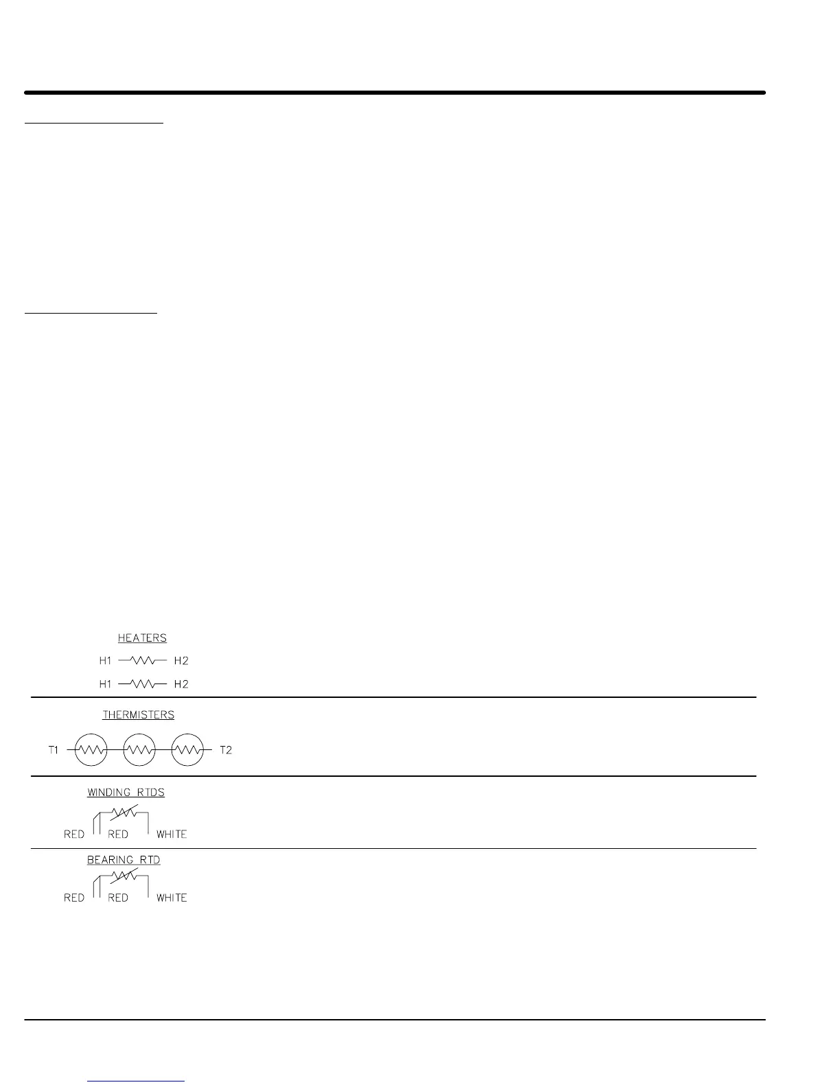
Figure 2‐1 Accessory Connections
One heater is installed in each end of motor.
Leads for each heater are labeled H1 & H2.
(Like numbers should be tied together).
Three thermisters are installed in windings and tied in series.
Leads are labeled T1 & T2.
Winding RTDs are installed in windings (2) per phase.
Each set of leads is labeled W1, W2, W3, W4, W5, & W6.
* One bearing RTD is installed in Drive endplate (PUEP), leads
are labeled RTDDE.
* One bearing RTD is installed in Opposite Drive endplate (FREP), leads
are labeled RTDODE.
* Note RTD may have 2-Red/1-White leads; or 2-White/1-Red Lead.
 Loading...