INSTALLATION
2-1. INTRODUCTION
This section contains information and instructions
necessary for the installation and shipping
of
the
Model 3440A series Voltmeters. Details are
provided for initial inspection, power connection,
grounding safety requirements, installation
information, and repacking instructions for storage
or shipment.
2-2. UNPACKING AND INITIAL
INSPECTION
Unpacking and handling
of
the voltmeter requires
only the normal precautions and procedures
applicable to the handling
of
sensitive electronic
equipment. The contents
of
all shipping containers
should be checked for included accessories and
certified against the packing slip to ascertain that
the shipment
is
complete.
2-3. PERFORMANCE CHECKS
This instrument
wa:,
carefully inspected for
mechanical and electrical performance before
shipment from the factory.
It
should be free
of
physical defects and
in
perfect electrical order upon
receipt. Check the instrument for damage
in
transit
and perform the electrical procedure outlined
in
paragraph 5-9.
If
there is indication
of
damage or
deficiency see the warranty
in
this manual and
notify your local Ballantine field engineering
representative or the
factory.
CA
UTION: It is recommended that the
operator be fully familiar with the
specifications
and
all sections
of
this
manual. Failure to do
so
may
compromise the warranty
and
the
accuracy which Ballantine has
engineered into
your
instrument.
2-4.
POWER
REQUIREMENTS
The instrument may be operated from
anyone
of
the following ac sources:
a.
90 to 100 V (100 V nominal)
b.
108 to 132 V (120 V nominal)
c.
198 to 242 V (200 V nominal)
d.
216 to 264 V (240 V nominal)
e.
All instruments operate over the power
frequency range
of
48 to 440 Hz. Always verify
that the operating line voltage
is
the same as that
specified on the rear panel power receptacle switch
plug. See Figure 2-1.
Section
2.
Installation
CAUTION: Failure to switch the
instrument to match the operating line
voltage will damage the instrument
and
may void the warranty.
f.
Internal rechargeable battery power supply;
(Optional) Option 05. A battery and charger are
installed
in
the voltmeter. A fully charged battery
will operate the instrument for 8 hours. When
operating
on
internal batteries, the pilot lamp also
indicates power ON operation and
is
illuminated to
act as a battery charge indicator as long as
sufficient battery charge
is
available to power the
instrument.
2-5. GROUNDING
REQUIREMENTS
To insure the safety
of
operating personnel, the
U.S. O.S.H.A. (Occupational Safety and Health)
requirement and good engineering practice mandate
that the instrument panel and enclosure be "earth"
grounded. All Ballantine instruments are provided
with an Underwriters Laboratories (U.L. and
C.S.A.) listed three-conductor power cable, which
when plugged into an appropriate power receptacle,
grounds the instrument. The long offset pin on the
male end
ofthe
power cable carries the ground wire
to the long pin
of
the Euro connector (DIN
standard) receptacle on the rear panel
of
the
instrument.
To preserve the safety protection feature when
operating the instrument from a two-contact outlet
use a three-prong to two-prong adapter and
connec~
the green lead
on
the adapter to
an
"earth" ground.
2-6. INSTALLATION AND
MOUNTING
The instrument
is
fully solid state and dissipates
minimal power. No special cooling
is
required.
However, the instrument should not be operated
where the ambient temperature exceeds 55°C
(131°F), when the relative humidity exceeds 95%
or condensation appears anywhere on the
instrument.
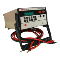
2-7. BENCH MOUNTING
The instrument
is
shipped with plastic feet and tilt
stand
in
place and ready for use as a bench or
portable instrument. See outline drawing Figure 2-2
for dimensions.
2-8. SHORT
T]~RM
STORAGE
If
the instrument
is
to be stored for a short period
of
time (less than three months) place cardboard over
page
2-1
N8AUM
 Loading...